Under construction!
How to check sensors and valves that may be causing issues.
Note: This is not inclusive, but can be a good guide for beginners.
Before I begin to explain any of this, it is important to understand how your internal combustion engine works. Your 97-03 is not as simply as a 70 model carburetor intake and engine. The PCM nearly controls and regulates every sensor your engine runs off of. Sensors are a huge part of why your engine runs smoothly and operates the way it does. If you are having any symptoms of Poor idle, Stalling, Poor drive-ability, ETC. Then the culprit could be a simple sensor, valve (controllable), or hose. Your PCM (power-train control module) monitors and reacts to each of these sensors, they are constantly sending information to the PCM and the PCM sends back a reaction. The concept seems simple, but the logic of how everything works in harmony can be very complex. This is why I wanted to go over how to check a few of the sensors your engine depends on to run in its maximum effective range (good drivability, good idle, no stalling, proper mpg, etc). I know a lot of you guys have acess to scan tools etc, but you can actually accomplish a lot with a little deductive reasoning and a simply $20 DMM (aka voltage and ohm meter). I highly suggest anyone to purchase a DMM, it is a valuable tool and can save you a lot of headaches.
I’m not going to go into detail with a( how-to) to replace all of these, but I will point out in each sensor what you need to look for when it is functioning properly. I will also denote the location and what voltage or resistance to look for when checking sensors and or controllable valves.
Index:
1. Exhaust Gas Recirculation (EGR) and Control Systems
2. Evaporative Emissions Control System (EVAP)
3. Positive Crankcase Ventilation (PCV) system
4. Engine Coolant Temperature (ECT) sensor
5. Mass Airflow Sensor (MAF)
6. Intake Air Temperature (IAT) sensor
7. Throttle Position Sensor (TPS)
8. Oxygen sensor
9. Brake On/Off (BOO) switch
There are other sensors such as the VSS, Fuel Pressure, etc. that are better left to a scan tool if you aren’t sure what to look for. I think the Index above should cover a lot of the general asked questions for “why is my truck surging” , “bad idle”, etc.
EGR- Exhaust Gas Recirculation (EGR) system
1) EGR – If a code is displayed there are several possibilities for EGR failure. Engine coolant temperature (ECT) sensor, TPS, MAF sensor, TCC system and the engine rpm govern the parameters the EGR system use for distinguishing the correct ON time.
Symptoms and codes of a BAD EGR Valve:
Car or truck runs fine, but the Check Engine Light is on
EGR Valve Fault Code:
P0401 EGR System Flow Insufficient.
P01406 EGR Valve Pintle Position.
Rough Idle.
Really BAD gas mileage.
Lack of power as you accelerate the vehicle down the road.
Truck seems to run okay above 30 miles and hour but once you come to an idle, the engine barely stays running and/or idles rough. Once you take off again, it runs OK.
About:
Exhaust Gas Recirculation (EGR) System
The purpose of the Exhaust Gas Recirculation (EGR) system on your engine is to limit oxides of nitrogen (NOx) emissions. This is done by redirecting small amounts of exhaust gas back through the upper intake to get mixed in with the air/fuel charge. The resultant diluted air/fuel mixture (i.e., less oxygen per cubic foot) burns cooler and combustion chamber temperatures are reduced accordingly, thereby lowering NOx emissions.
The Ford DPFE/EGR system is controlled by the Powertrain Control Module (PCM). The system employs an EGR Valve, an Electronic Vacuum Regulator (EVR), and a Delta Pressure Feedback EGR sensor (DPFE).
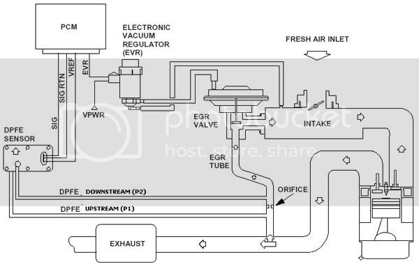
- The EGR valve is mounted on (or very close) to the upper intake and is connected to both the intake and the exhaust system by virtue of a special EGR Tube. The valve has a vacuum port that allows it to be controlled (opened and closed) by the EVR. When the valve is open, exhaust gas flows into the upper intake and mixes with the a/f charge.
**Very obvious, it is the piece with the large circular top** All parts enclosed inside it.
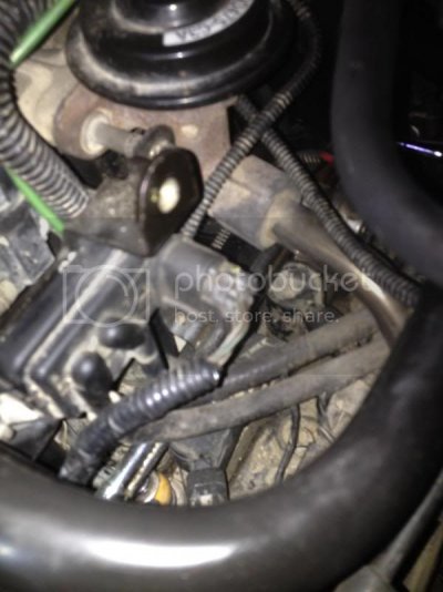
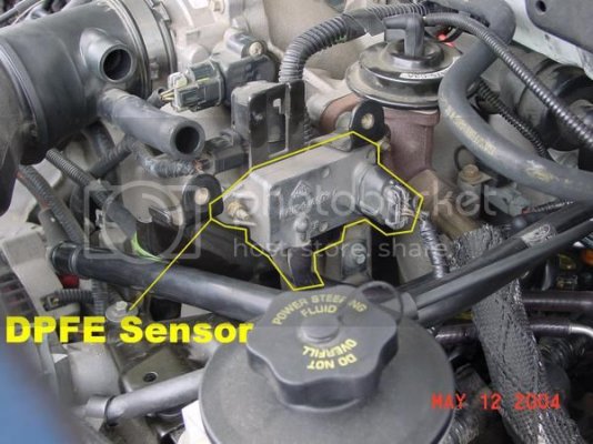
- The DPFE Sensor measures EGR flow across an orifice located inside the special EGR Tube. The orifice is positioned between two hose ports coming off the tube which are connected to the DPFE sensor with special heat-resistant hoses. When the EGR Valve is open, a pressure differential is created across the orifice (intake manifold pressure vs. exhaust pressure). By design, this difference in pressure is measured by the DPFE sensor in terms of voltage. The DPFE voltage signal output to the PCM is directly proportional to the flow of exhaust gas entering the intake manifold.
The PCM determines optimal conditions for EGR flow and then, based on the DPFE voltage signal and some other sensor data, activates the EVR to open and close the EGR valve as necessary.
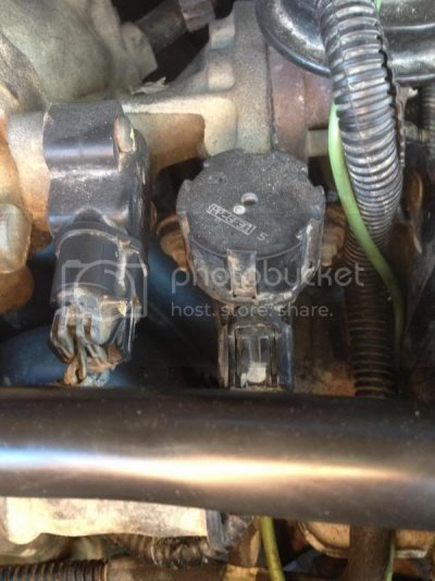
- The EVR is a solenoid with two vacuum ports. One port is connected to a vacuum source/supply, and the other is connected to the EGR valve. There is also a passage that vents vacuum to the atmosphere. A disc inside the solenoid is moved by electro-magnetic force, as directed by the PCM. If more EGR flow is required, the PCM increases the duty-cycle to the EVR, moving the disc to close off the atmospheric vent, which in turn increases the amount of vacuum flow to the EGR valve. If less EGR flow is desired, the PCM decreases the duty-cycle to the EVR, allowing for more atmospheric venting and hence less vacuum flow to the EGR valve.
The EVR is a "normally closed" solenoid, which means that when it is de-energized, the position of the disc allows for maximum venting to the atmosphere (resulting in negligible vacuum flow to the EGR valve).
EVR is on the right with the Circular top. It is next to the DPFE.
Note that Ford EGR systems DO NOT engage when:
1) The engine is cold ;
2 ) The engine is at idle;
3 ) The engine is at WOT;
4) At low ambient temps (water vapor from the exhaust can freeze on the throttle plate).
All credit goes to: Part 1 -How to Test the Ford EGR Valve and DPFE Sensor.
How to check:
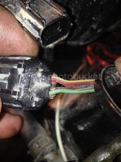
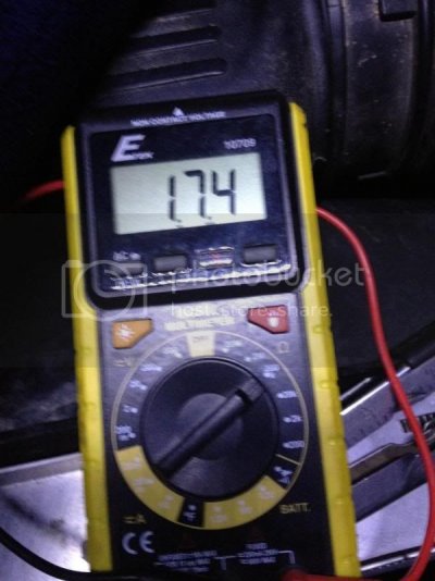
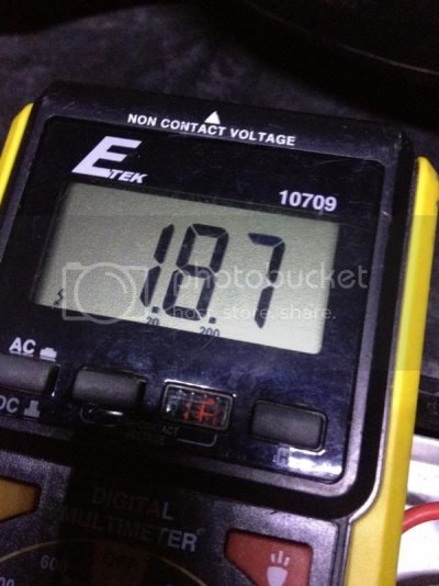
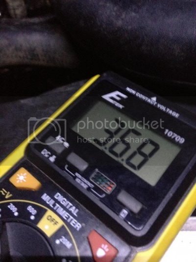
To check the EGR vacuum regulator, disconnect the electrical connector to the EGR vacuum regulator, turn the ignition key ON and check for battery voltage to the solenoid (see picture below) . Battery voltage should be present 12V+.
The Right terminal should be Red/Yellow for +12V, left terminal Pink/Black is GRD
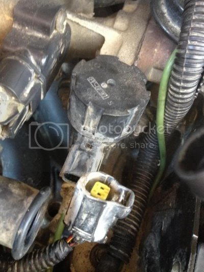
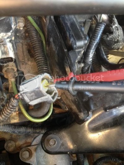
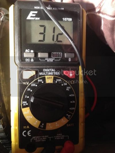
Next, use an ohmmeter and check the resistance of the EGR vacuum regulator. It should anywhere from 30-70 ohms
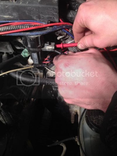
Unplug the two prong sensor as in the previous step and use your ohmeter to prob the two terminals.
When doing this, make sure the prob the right terminal (Red/Yellow with the red prob) The other terminal is for the Black probe.
Check for reference voltage to the DPFE sensor. With the ignition key on (engine not running), check for voltage on the harness side of the electrical connector on terminal VREF. It should be between 4.0 and 6.0 volts. If the test results are incorrect, replace the DPFE sensor.
This is a 3 prong connector. Top Prong is Brown/Green, Middle Prong is Grey/Red, Bottom Prong is Brown/White.
Top= Brown/Green= Signal to ECM
Middle = Grey/Red = GND
Bottom = Brown/White = REF
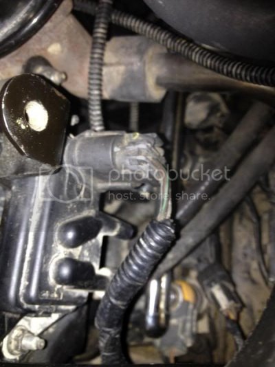
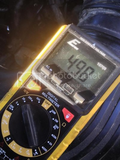
With the engine cold there should be NO EGR therefore the voltage should be approximately 0.20 to 0.70 volts. As the engine starts to warm and EGR is signaled by the computer, voltage values should increase to approximately 4.0 to 6.0 volts.
How to check sensors and valves that may be causing issues.
Note: This is not inclusive, but can be a good guide for beginners.
Before I begin to explain any of this, it is important to understand how your internal combustion engine works. Your 97-03 is not as simply as a 70 model carburetor intake and engine. The PCM nearly controls and regulates every sensor your engine runs off of. Sensors are a huge part of why your engine runs smoothly and operates the way it does. If you are having any symptoms of Poor idle, Stalling, Poor drive-ability, ETC. Then the culprit could be a simple sensor, valve (controllable), or hose. Your PCM (power-train control module) monitors and reacts to each of these sensors, they are constantly sending information to the PCM and the PCM sends back a reaction. The concept seems simple, but the logic of how everything works in harmony can be very complex. This is why I wanted to go over how to check a few of the sensors your engine depends on to run in its maximum effective range (good drivability, good idle, no stalling, proper mpg, etc). I know a lot of you guys have acess to scan tools etc, but you can actually accomplish a lot with a little deductive reasoning and a simply $20 DMM (aka voltage and ohm meter). I highly suggest anyone to purchase a DMM, it is a valuable tool and can save you a lot of headaches.
I’m not going to go into detail with a( how-to) to replace all of these, but I will point out in each sensor what you need to look for when it is functioning properly. I will also denote the location and what voltage or resistance to look for when checking sensors and or controllable valves.
Index:
1. Exhaust Gas Recirculation (EGR) and Control Systems
2. Evaporative Emissions Control System (EVAP)
3. Positive Crankcase Ventilation (PCV) system
4. Engine Coolant Temperature (ECT) sensor
5. Mass Airflow Sensor (MAF)
6. Intake Air Temperature (IAT) sensor
7. Throttle Position Sensor (TPS)
8. Oxygen sensor
9. Brake On/Off (BOO) switch
There are other sensors such as the VSS, Fuel Pressure, etc. that are better left to a scan tool if you aren’t sure what to look for. I think the Index above should cover a lot of the general asked questions for “why is my truck surging” , “bad idle”, etc.
EGR- Exhaust Gas Recirculation (EGR) system
1) EGR – If a code is displayed there are several possibilities for EGR failure. Engine coolant temperature (ECT) sensor, TPS, MAF sensor, TCC system and the engine rpm govern the parameters the EGR system use for distinguishing the correct ON time.
Symptoms and codes of a BAD EGR Valve:
Car or truck runs fine, but the Check Engine Light is on
EGR Valve Fault Code:
P0401 EGR System Flow Insufficient.
P01406 EGR Valve Pintle Position.
Rough Idle.
Really BAD gas mileage.
Lack of power as you accelerate the vehicle down the road.
Truck seems to run okay above 30 miles and hour but once you come to an idle, the engine barely stays running and/or idles rough. Once you take off again, it runs OK.
About:
Exhaust Gas Recirculation (EGR) System
The purpose of the Exhaust Gas Recirculation (EGR) system on your engine is to limit oxides of nitrogen (NOx) emissions. This is done by redirecting small amounts of exhaust gas back through the upper intake to get mixed in with the air/fuel charge. The resultant diluted air/fuel mixture (i.e., less oxygen per cubic foot) burns cooler and combustion chamber temperatures are reduced accordingly, thereby lowering NOx emissions.
The Ford DPFE/EGR system is controlled by the Powertrain Control Module (PCM). The system employs an EGR Valve, an Electronic Vacuum Regulator (EVR), and a Delta Pressure Feedback EGR sensor (DPFE).

- The EGR valve is mounted on (or very close) to the upper intake and is connected to both the intake and the exhaust system by virtue of a special EGR Tube. The valve has a vacuum port that allows it to be controlled (opened and closed) by the EVR. When the valve is open, exhaust gas flows into the upper intake and mixes with the a/f charge.
**Very obvious, it is the piece with the large circular top** All parts enclosed inside it.

- The DPFE Sensor measures EGR flow across an orifice located inside the special EGR Tube. The orifice is positioned between two hose ports coming off the tube which are connected to the DPFE sensor with special heat-resistant hoses. When the EGR Valve is open, a pressure differential is created across the orifice (intake manifold pressure vs. exhaust pressure). By design, this difference in pressure is measured by the DPFE sensor in terms of voltage. The DPFE voltage signal output to the PCM is directly proportional to the flow of exhaust gas entering the intake manifold.
The PCM determines optimal conditions for EGR flow and then, based on the DPFE voltage signal and some other sensor data, activates the EVR to open and close the EGR valve as necessary.

- The EVR is a solenoid with two vacuum ports. One port is connected to a vacuum source/supply, and the other is connected to the EGR valve. There is also a passage that vents vacuum to the atmosphere. A disc inside the solenoid is moved by electro-magnetic force, as directed by the PCM. If more EGR flow is required, the PCM increases the duty-cycle to the EVR, moving the disc to close off the atmospheric vent, which in turn increases the amount of vacuum flow to the EGR valve. If less EGR flow is desired, the PCM decreases the duty-cycle to the EVR, allowing for more atmospheric venting and hence less vacuum flow to the EGR valve.
The EVR is a "normally closed" solenoid, which means that when it is de-energized, the position of the disc allows for maximum venting to the atmosphere (resulting in negligible vacuum flow to the EGR valve).
EVR is on the right with the Circular top. It is next to the DPFE.

Note that Ford EGR systems DO NOT engage when:
1) The engine is cold ;
2 ) The engine is at idle;
3 ) The engine is at WOT;
4) At low ambient temps (water vapor from the exhaust can freeze on the throttle plate).
All credit goes to: Part 1 -How to Test the Ford EGR Valve and DPFE Sensor.
How to check:
To check the EGR vacuum regulator, disconnect the electrical connector to the EGR vacuum regulator, turn the ignition key ON and check for battery voltage to the solenoid (see picture below) . Battery voltage should be present 12V+.
The Right terminal should be Red/Yellow for +12V, left terminal Pink/Black is GRD


Next, use an ohmmeter and check the resistance of the EGR vacuum regulator. It should anywhere from 30-70 ohms
Unplug the two prong sensor as in the previous step and use your ohmeter to prob the two terminals.
When doing this, make sure the prob the right terminal (Red/Yellow with the red prob) The other terminal is for the Black probe.
Check for reference voltage to the DPFE sensor. With the ignition key on (engine not running), check for voltage on the harness side of the electrical connector on terminal VREF. It should be between 4.0 and 6.0 volts. If the test results are incorrect, replace the DPFE sensor.
This is a 3 prong connector. Top Prong is Brown/Green, Middle Prong is Grey/Red, Bottom Prong is Brown/White.
Top= Brown/Green= Signal to ECM
Middle = Grey/Red = GND
Bottom = Brown/White = REF

With the engine cold there should be NO EGR therefore the voltage should be approximately 0.20 to 0.70 volts. As the engine starts to warm and EGR is signaled by the computer, voltage values should increase to approximately 4.0 to 6.0 volts.


