You are using an out of date browser. It may not display this or other websites correctly.
You should upgrade or use an alternative browser.
You should upgrade or use an alternative browser.
2007 expedition El, driver's lowbeam not working
- Thread starter jac21
- Start date
Disclaimer: Links on this page pointing to Amazon, eBay and other sites may include affiliate code. If you click them and make a purchase, we may earn a small commission.
Bedrck47
Full Access Members
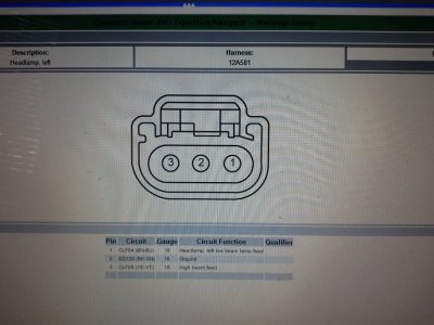
Ok Now take you ohm meter and with both connectors disconnected place one lead on the brown/blue wire and the other lead on a good ground read the resistance
Resistance is 0.6 ohms.
there have to be module that controls the lights cause according to the manual there is no relay for the low-beams. there is probably a cold solder in one of the resistors or contacts but i don't know were is located.
there have to be module that controls the lights cause according to the manual there is no relay for the low-beams. there is probably a cold solder in one of the resistors or contacts but i don't know were is located.
Bedrck47
Full Access Members
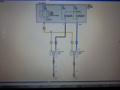
The low beams are controlled by FET transistors which are part of the Smart Junction Box (fuse box)
Principles of Operation
The smart junction box (SJB) monitors the headlamp switch position by sending voltage reference signals on multiple circuits to the headlamp switch. At any given time, one of the signal circuits is routed to ground. If the SJB does not detect any of the inputs to the headlamp switch is active (routed to ground) for 5 seconds, the SJB turns on the exterior lights and keeps them on for 10 minutes after the ignition switch is turned off (or 10 minutes from the time the SJB does not detect any headlamp switch input if the ignition switch was already off). If the SJB detects multiple circuits short to ground, the SJB implements a planned strategy depending on the multiple inputs received. If either of these situations occur, the SJB should NOT be ruled immediately as being at fault. This is normal behavior of the SJB design as it has detected a fault with the inputs from the headlamp switch.
The SJB also monitors the multifunction switch for a flash-to-pass or high beam request. There are 2 voltage reference circuits which monitor this. When the multifunction switch is in the FLASH-TO-PASS or HIGH BEAM position, the voltage signal is routed to ground.
NOTE: For Navigator, the high beam indicator does not illuminate with the flash-to-pass feature.
NOTE: The flash-to-pass feature does not require any input from the headlamp switch.
When the SJB receives an input requesting the headlamps on, the SJB supplies voltage to the low beams. If the low beams are on and the SJB receives a request for high beams (or just a flash-to-pass request), the SJB energizes an internal relay which routes voltage to the headlamps (and flash-to-pass lamps for Navigator).
Field-Effect Transistor (FET) Protection
The SJB utilizes a FET protective circuit strategy for many of its outputs (for example, the headlamp output circuit). Output loads (current level) are monitored for excessive current (typically short circuits) and are shut down (turns off the voltage or ground provided by the module) when a fault is detected. A continuous DTC is stored at that time for the fault. The circuit will then reset after a customer demand of the function (switching the component on, 30-minute battery saver being energized). When an excessive circuit load occurs several times, the module shuts down the output until a repair procedure is carried out. At the same time, the continuous DTC that was stored on the first failure will not clear by a command to clear the continuous DTCs. The module will not allow this code to be cleared or the circuit restored to normal until a successful on-demand self-test proves that the fault has been repaired. After the on-demand self-test has successfully completed (no on-demand DTCs present), the continuous DTC will have been cleared and the circuit function will return.
The SJB FET protected output circuits for the headlamp system are for the LH low beam output and the RH low beam output circuits.
Inspection and Verification
NOTE: Make sure the multifunction switch is in the LOW BEAM position.
Principles of Operation
The smart junction box (SJB) monitors the headlamp switch position by sending voltage reference signals on multiple circuits to the headlamp switch. At any given time, one of the signal circuits is routed to ground. If the SJB does not detect any of the inputs to the headlamp switch is active (routed to ground) for 5 seconds, the SJB turns on the exterior lights and keeps them on for 10 minutes after the ignition switch is turned off (or 10 minutes from the time the SJB does not detect any headlamp switch input if the ignition switch was already off). If the SJB detects multiple circuits short to ground, the SJB implements a planned strategy depending on the multiple inputs received. If either of these situations occur, the SJB should NOT be ruled immediately as being at fault. This is normal behavior of the SJB design as it has detected a fault with the inputs from the headlamp switch.
The SJB also monitors the multifunction switch for a flash-to-pass or high beam request. There are 2 voltage reference circuits which monitor this. When the multifunction switch is in the FLASH-TO-PASS or HIGH BEAM position, the voltage signal is routed to ground.
NOTE: For Navigator, the high beam indicator does not illuminate with the flash-to-pass feature.
NOTE: The flash-to-pass feature does not require any input from the headlamp switch.
When the SJB receives an input requesting the headlamps on, the SJB supplies voltage to the low beams. If the low beams are on and the SJB receives a request for high beams (or just a flash-to-pass request), the SJB energizes an internal relay which routes voltage to the headlamps (and flash-to-pass lamps for Navigator).
Field-Effect Transistor (FET) Protection
The SJB utilizes a FET protective circuit strategy for many of its outputs (for example, the headlamp output circuit). Output loads (current level) are monitored for excessive current (typically short circuits) and are shut down (turns off the voltage or ground provided by the module) when a fault is detected. A continuous DTC is stored at that time for the fault. The circuit will then reset after a customer demand of the function (switching the component on, 30-minute battery saver being energized). When an excessive circuit load occurs several times, the module shuts down the output until a repair procedure is carried out. At the same time, the continuous DTC that was stored on the first failure will not clear by a command to clear the continuous DTCs. The module will not allow this code to be cleared or the circuit restored to normal until a successful on-demand self-test proves that the fault has been repaired. After the on-demand self-test has successfully completed (no on-demand DTCs present), the continuous DTC will have been cleared and the circuit function will return.
The SJB FET protected output circuits for the headlamp system are for the LH low beam output and the RH low beam output circuits.
Inspection and Verification
- Verify the customer concern.
- Visually inspect the following for obvious signs of mechanical or electrical damage.
Visual Inspection Chart
Mechanical Electrical- Headlamp switch
- Multifunction switch
- Headlamp assembly
- Battery junction box (BJB) fuse(s):
- 44 (20A) (LH high intensity discharge [HID] headlamp)
- 48 (20A) (RH HID headlamp)
- Smart junction box (SJB) fuse(s):
- 7 (10A) (LH low beam)
- 8 (10A) (RH low beam)
- 23 (15A) (high beams)
- Ballast
- SJB
- Bulb(s)
- Circuitry
- If an obvious cause for an observed or reported concern is found, correct the cause (if possible) before proceeding to the next step.
NOTE: Make sure the multifunction switch is in the LOW BEAM position.
- NOTE: Make sure to use the latest scan tool software release.
If the cause is not visually evident, connect the scan tool to the data link connector (DLC).
- NOTE: The vehicle communication module (VCM) LED prove-out confirms power and ground from the DLC are provided to the VCM.
If the scan tool does not communicate with the VCM:- Check the VCM connection to the vehicle.
- Check the scan tool connection to the VCM.
- Refer to Section 418-00 , No Power To The Scan Tool, to diagnose no communication with the scan tool.
- If the scan tool does not communicate with the vehicle:
- Verify the ignition key is in the ON position.
- Verify the scan tool operation with a known good vehicle.
- Refer to Section 418-00 to diagnose no response from the powertrain control module (PCM).
- Carry out the network test.
- If the scan tool responds with no communication for one or more modules, refer to Section 418-00 .
- If the network test passes, retrieve and record the continuous memory DTCs.
- Clear the continuous DTCs and carry out the self-test diagnostics for the SJB.
- If the DTCs retrieved are related to the concern, go to the Smart Junction Box (SJB) Diagnostic Trouble Code (DTC) Chart. For all other DTCs, refer to Section 419-10 .
- If no DTCs related to the concern are retrieved, GO to Symptom Chart .
Bedrck47
Full Access Members
- One low beam headlamp is inoperative
- Fuse
- Circuitry
- High intensity discharge (HID) relay
- HID bulb
- Headlamp assembly
- Ballast
- SJB
Bedrck47
Full Access Members
Bedrck47
Full Access Members
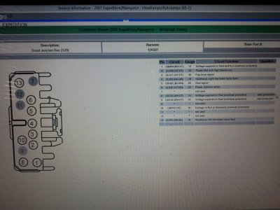
What has me confused is that you have 13.6 volts at pin 13 but not at C1021
Similar threads
- Replies
- 1
- Views
- 509
- Replies
- 5
- Views
- 1K
- Replies
- 5
- Views
- 999


