Power windows won't work

Disclaimer: Links on this page pointing to Amazon, eBay and other sites may include affiliate code. If you click them and make a purchase, we may earn a small commission.

OP
OP
J

joeytforrest

Active Member
Joined
Jun 14, 2015
Posts
31
Reaction score
0
Location
Houston
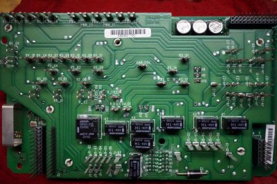
If F33 is fuse slot 33 on the sjb, yes, it is there with connections... Listed as spare on the diagram.

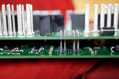
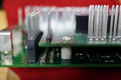
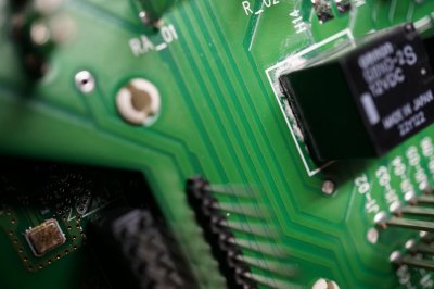
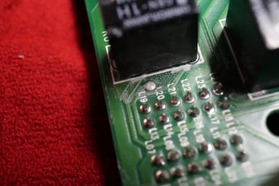
White powder is water damage? Can this be cleaned and does it sometime result in working component?
 

Attachments

  • DSC01056.jpg
    DSC01056.jpg
    102.9 KB · Views: 28
  • DSC01057.jpg
    DSC01057.jpg
    86.5 KB · Views: 27
  • DSC01060.jpg
    DSC01060.jpg
    89.8 KB · Views: 25
Last edited:

stamp11127

Full Access Members
Joined
Mar 10, 2012
Posts
6,218
Reaction score
1,250
Location
Temple, Georgia
There is a wax type coating on both sides of the boards for basic protection from the elements. I wouldn't worry about the white markings on some spots.

It looks like the buttons that hold the boards together can be squeezed so that one board may be removed from the other. I can't see them manufacturing them as an assembly.
 
OP
OP
J

joeytforrest

Active Member
Joined
Jun 14, 2015
Posts
31
Reaction score
0
Location
Houston
The white spacers are only connected to one side and are truly spacers - they don't connect the boards. I've been looking for anything else that connects the boards and all I can find are the tines.

The tines in the pictures, from my observation, seem to be soldered to both boards and even when I start putting a little of my 280lbs into it, they aren't budging.
 

Attachments

  • DSC01064.jpg
    DSC01064.jpg
    87.7 KB · Views: 17
  • DSC01065.jpg
    DSC01065.jpg
    84 KB · Views: 18
  • DSC01066.jpg
    DSC01066.jpg
    81.2 KB · Views: 20

stamp11127

Full Access Members
Joined
Mar 10, 2012
Posts
6,218
Reaction score
1,250
Location
Temple, Georgia
May as well put it back together and decide which option you would like to pursue: repair, replace or modify.
 
OP
OP
J

joeytforrest

Active Member
Joined
Jun 14, 2015
Posts
31
Reaction score
0
Location
Houston
Thank you for the load of help to date, Stamp.

I think with regard to repair, I've probably gone as far as I can go in my own garage. I question my soldering skills with a pcb. Also, I have a modified sjb that works as of now so any further work runs the risk of replacement. I'll likely stick with the modified jumper for now.

Again, thank you for your time and expertise that you've freely given. Same goes for Bedrck.
 

stamp11127

Full Access Members
Joined
Mar 10, 2012
Posts
6,218
Reaction score
1,250
Location
Temple, Georgia
The only soldering skills needed would be for the external addition to the fuse box - just extending wires on a relay socket, adding terminals and then plugging in.

If you are interested I can whip up a wiring diagram with parts list and send it sometime tomorrow.
 
Last edited:
OP
OP
J

joeytforrest

Active Member
Joined
Jun 14, 2015
Posts
31
Reaction score
0
Location
Houston
I would certainly give it a go but I thought I was at a roadblock based on your comment since I couldn't separate the boards.
 
Last edited:
OP
OP
J

joeytforrest

Active Member
Joined
Jun 14, 2015
Posts
31
Reaction score
0
Location
Houston
I've been given this some thought (so stop me before I hurt myself!).

According to the 07 wiring diagram provided by Bedrck, 30 and 86 are hot all the times. Load side of the relay is good but we have determined that 85 is the fault on the control side.

Is there a way to properly ground 85 without soldering in a new relay harness? Can I tie into F33 or F34 which are both spares and adjacent to relay at 48?
 
Last edited:

stamp11127

Full Access Members
Joined
Mar 10, 2012
Posts
6,218
Reaction score
1,250
Location
Temple, Georgia
"According to the 07 wiring diagram provided by Bedrck, 30 and 86 are hot all the times. Load side of the relay is good but we have determined that 85 is the fault on the control side." Correct - we just don't know where the failure is.


There are two variations on the relay sockets that are available. One has long leads and the other has short leads. If you were to get the socket with short leads, you would have to solder & heatshrink longer wires onto them. There wouldn't be a need to modify the sjb, it would be plug and play.

Links below are for examples:

Long leads:
1977 1982 Corvette Fog Driving Light High Output Relay Harness Kit | eBay

Short leads:
1 Pack The Install Bay 30 40 Amp Relay Harness SPDT 12V Bosch Style | eBay

Branch Circuit Harness - for F33 to power coil on relay:
ATM Fuse Plug Add A Circuit Fuse Block Extension for ATM for ATM Mini Fuse | eBay

The main idea is to move the control side of the acc delay relay to F33 which is hot in run/start instead of F47. Power windows would only work with the ignition in run/start.

Another advantage is that in the future should you decide to swap out the sjb, it is just a matter of removing the old box, installing the new one then program. No need to connect the external relay.
 
Last edited:
OP
OP
J

joeytforrest

Active Member
Joined
Jun 14, 2015
Posts
31
Reaction score
0
Location
Houston
Alright, long leads and branch circuit... A question is sticking in my mind but don't feel the need to answer because although the "why" is important, the "how" is more important. I can read up more to close my gaps. On this circuit, isn't F47 after the relay and on the power window side of the circuit and would operate normally only if 85 of the relay would properly connect to ground?

Here's where my confusion reigns supreme but I took a stab at how to wire. I hope this doesn't display my total ignorance:

*Branch circuit - branch fuse inserted into F33. Lead of branch circuit soldered to 86 lead of relay harness. What amp is my secondary fuse?

*30 lead of relay harness - insert into slot 30 of existing relay using male spade connector (or do I need to find wire in harness and solder?)

*87 lead of relay harness - insert into slot 87 of existing relay using male spade connector (or do I need to find wire in harness and solder?)

*85 lead of relay harness - is this where I need a good ground?
 
Last edited:
Top