
soldatlamour
Active Member
Thermo - thanks for the advice
I don't weld, but I found a welder nearby. He's going to weld 12 tabs ( 4, 3, 3, 2) to my basket rack. I bought 20 tabs for a total of $3.40, and he's going to charge me only $60 to weld. I feel happy about it.
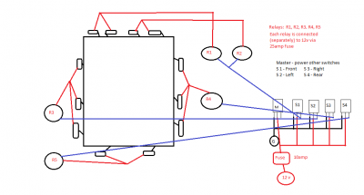
Please comment on my suggested plan of attack for wiring (diagram attached). I want to have a Master switch that "turns on" the other switches. My thought is that I'll have to run only one Power and one Ground (from the M switch) - the other switches' powers/grounds will run a few inches to the Master. Then the 4 switches will run to their respective relays.
I can split the load on S1 to two separate relays, right?
I plan on using 12 AWG wire from the lights to the relays. Let me know if that's OK. Also - with 4 lights ( all lights are 55w ) on the front, 3 on the sides and 2 on the back, will 25amp fuse for each of the relays be sufficient? (Since I'm splitting the front into two relays, perhaps the focus should be on the 3 55w side lights per relay ? )
What size wire should I run on the switches? Is a 10amp fuse good for the switches?
I've found a pocket in the back of the vehicle where I will put a Power distribution center. I plan on making a quick connect between the wires on the rack and the wiring from the distribution center (essentially, the 5 "loads" from the relays and a main grounding wire).
Thank you in advance for your help.
I don't weld, but I found a welder nearby. He's going to weld 12 tabs ( 4, 3, 3, 2) to my basket rack. I bought 20 tabs for a total of $3.40, and he's going to charge me only $60 to weld. I feel happy about it.
Please comment on my suggested plan of attack for wiring (diagram attached). I want to have a Master switch that "turns on" the other switches. My thought is that I'll have to run only one Power and one Ground (from the M switch) - the other switches' powers/grounds will run a few inches to the Master. Then the 4 switches will run to their respective relays.
I can split the load on S1 to two separate relays, right?
I plan on using 12 AWG wire from the lights to the relays. Let me know if that's OK. Also - with 4 lights ( all lights are 55w ) on the front, 3 on the sides and 2 on the back, will 25amp fuse for each of the relays be sufficient? (Since I'm splitting the front into two relays, perhaps the focus should be on the 3 55w side lights per relay ? )
What size wire should I run on the switches? Is a 10amp fuse good for the switches?
I've found a pocket in the back of the vehicle where I will put a Power distribution center. I plan on making a quick connect between the wires on the rack and the wiring from the distribution center (essentially, the 5 "loads" from the relays and a main grounding wire).
Thank you in advance for your help.