Bolt-on
Member
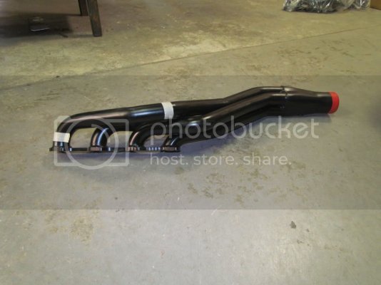
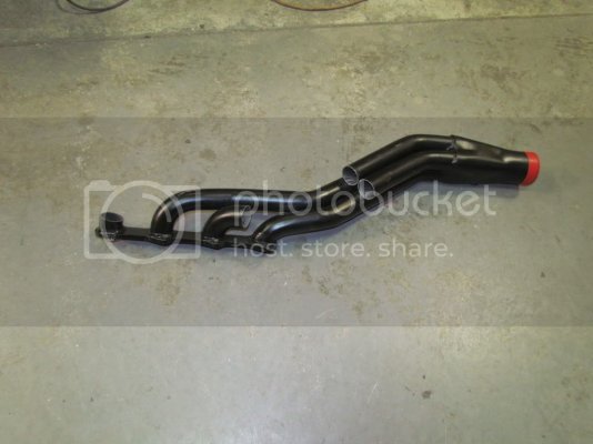
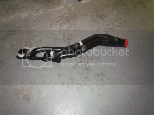
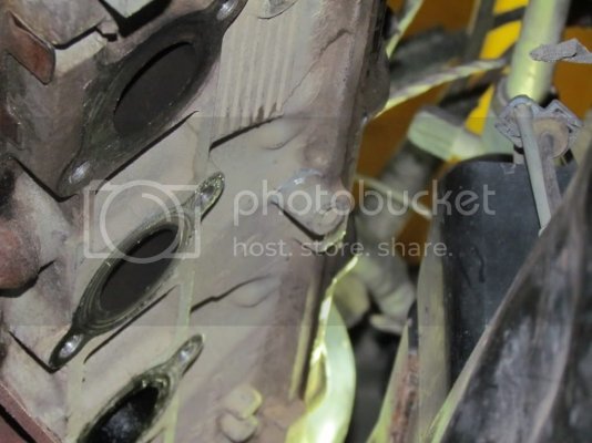
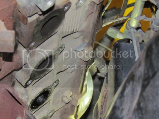
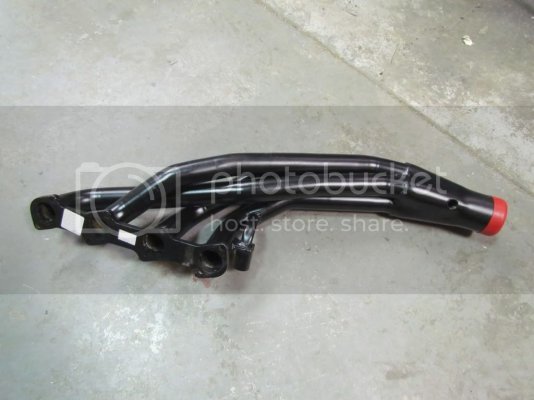
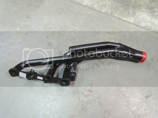
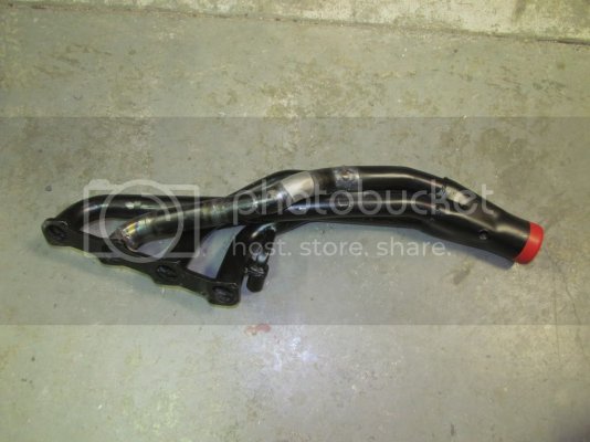
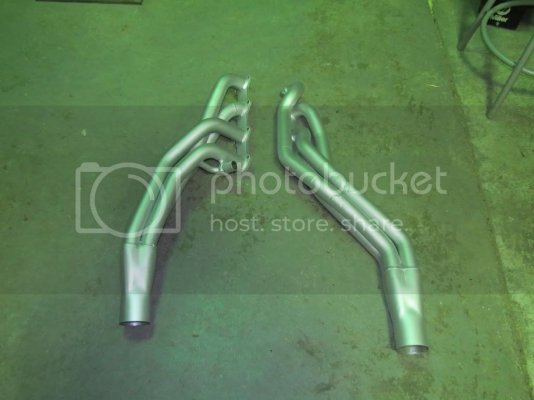
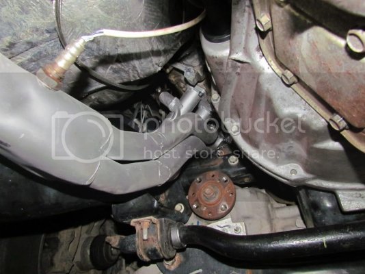
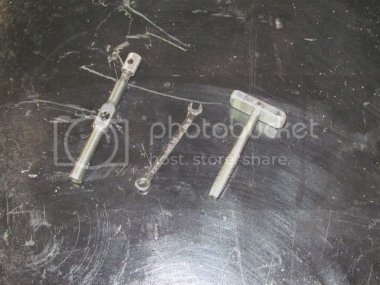
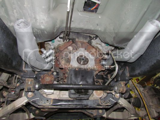
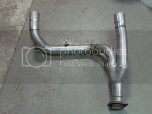
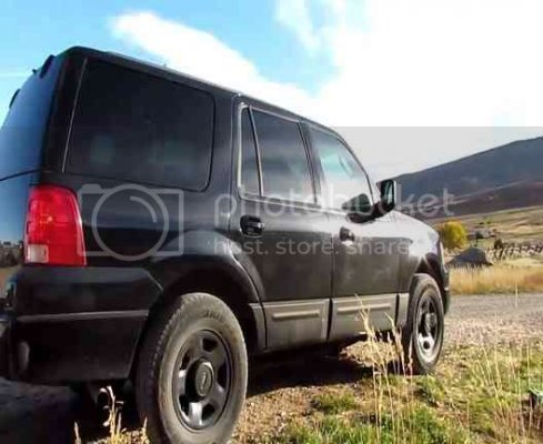
I just finished installing a 6-speed on my '03 Expedition (former cop car). I put headers on too while I was in there. The headers were twice the work of the tranny swap. I had to modify Pacesetter 70-2227 headers to clear the frame and drive shaft. Two header bolts were sheared off. The bolts are almost impossible to get to, and all the threads in the heads needed to be chased.
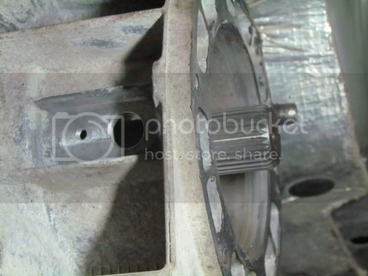
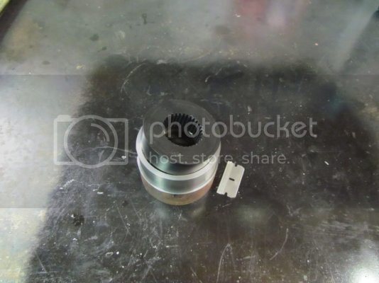
As far as I know, the only manual transmission that Ford used with the MOD 5.4 is the ZF 6 speed. Unfortunately, it is 4 3/16" longer than the auto and has a larger output shaft. I discovered this after I started taking things apart.
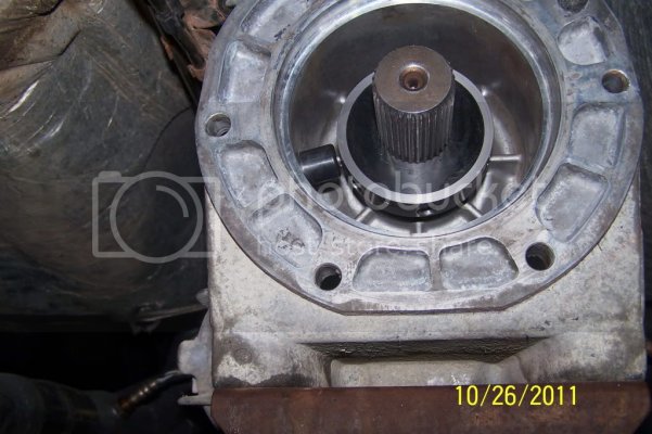
This is the output shaft on the auto.
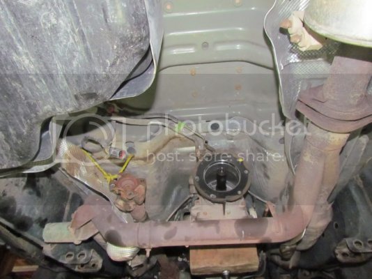
I could have used a transfer case from an F250, but I wanted the all-wheel-drive and I figured I might as well stick with the electric transfer case shifter. I measured carefully and decided the extra length would not be a problem. The fuel tank looks like it was made for the longer tranny.
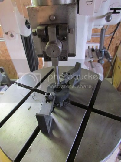
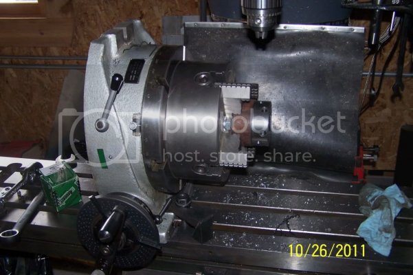
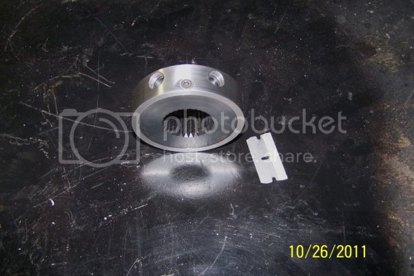
I called Moser Engineering to see if they could re-spline the 6-speed output on the main shaft to fit the Borg Warner T/C. The answer was "$65" so I disassembled the tranny and sent off the shaft. I disassembled the transfer case too and sent the input for matching. They said turnaround would be a couple of days.
Meanwhile I installed the clutch pedal and cut a hole in the floor for the shifter.
I had ordered a pedal assembly for an '03 F250. The brake master cylinder holes and an alignment pin lined up with the Expedition perfectly. There were two upper mounting bolt holes in the F150 pedal bracket that didn't have holes in the Expy. I scribed and drilled holes, then put access holes next to them for the clip nuts. It was a cramped and nasty job. I removed the steering column to do it.
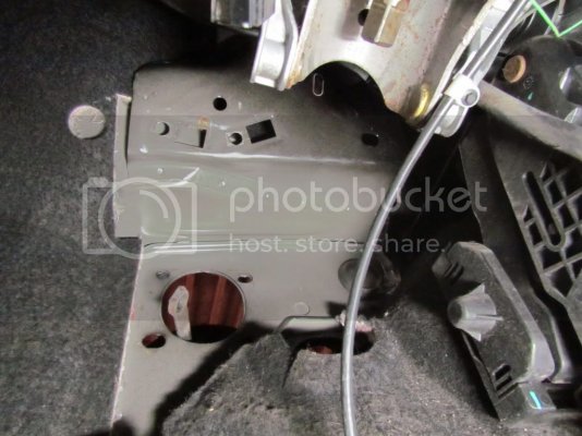
My Expy had electrically adjustable pedals. I could have made a heroic effort and saved that feature, but I ditched it.
Pedal assemblies side by side.
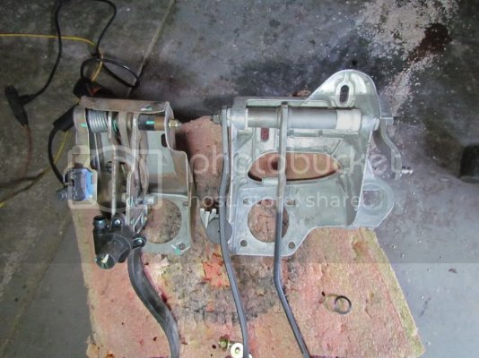
The peg for the master cylinder rod on the brake pedal was too high. I relocated it. The clutch slave cylinder arm on the right side of the pedal assembly interfered slightly with the steering column, so I ground the arm for clearance.
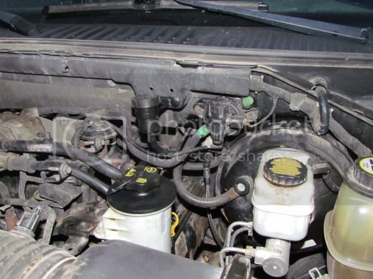
The clutch slave cylinder location had a rubber plug in the firewall, and mounting holes for the reservoir. It went right in. The hydraulic line I got for an F150 had the wrong lower end for the F250 6-speed. The F250 has the clutch master to the left of the brake master. The F150/Expy is on the right. The stock lines are hard plastic so they don't re-shape very well. I got fittings and a line from Summit Racing. Russell 641001 and Aeroquip FPBA0049-36.
Doing the layout for the hole.
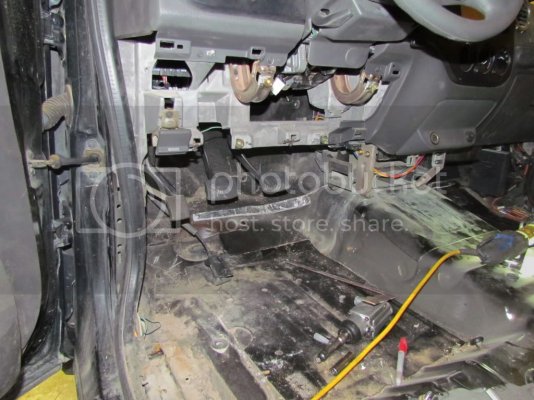
Cut out. I used the empty transmission housing to check the location. It was nice and light. The 6-speed weighs 240 pounds assembled.
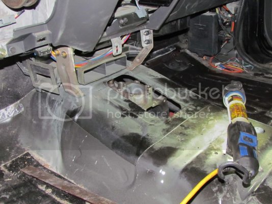
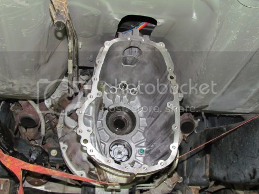
From the bottom.
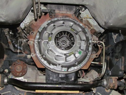
I installed a real flywheel and the clutch.
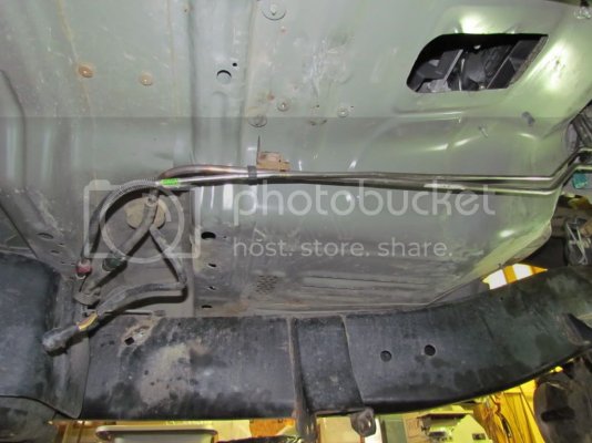
The fuel lines needed to be moved because the 6-speed is taller and wider at the top. I bent the return line in place, but had to remove the feed line and heat it to bend it without crimping.
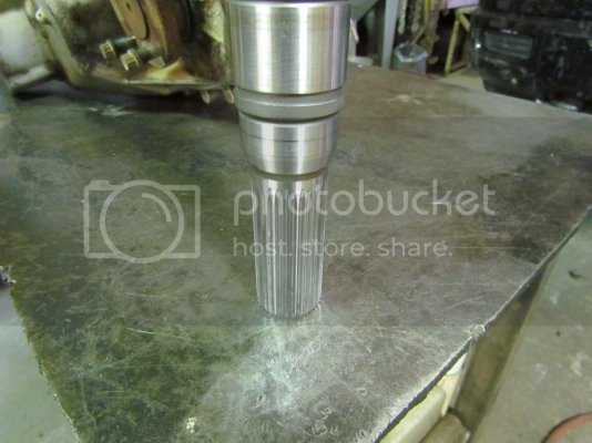
Meanwhile, the mainshaft came back. Here's the re-spline.
Here's the gear cluster going back together.
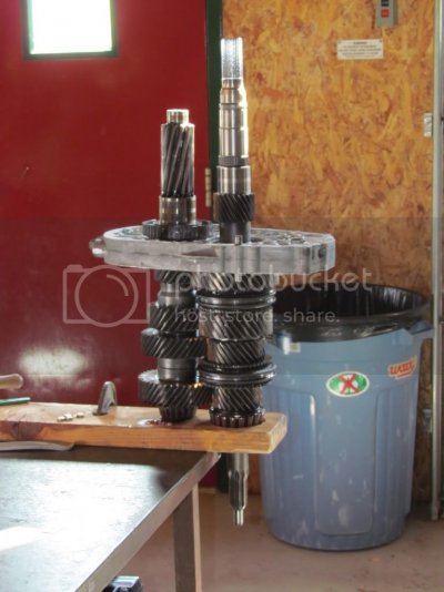
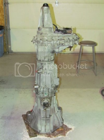
Here's the tranny and transfer case all put back together and stacked.
I needed to relocate the transmission cross member back about a foot. I cut the original mounts off.
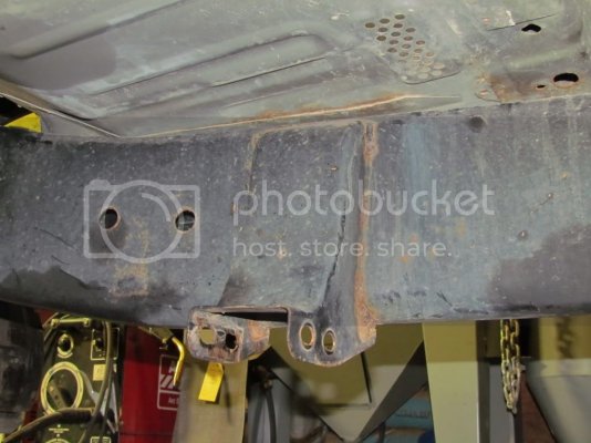
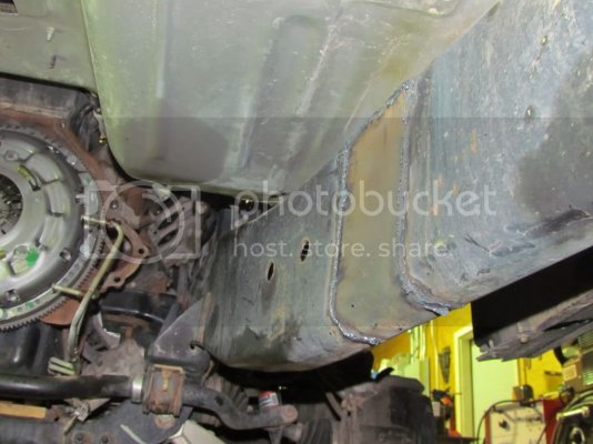
The original cross member was not long enough and too tall for the 6-speed. I used a piece of 1/8' wall 2" x 4" rectangular tubing for a cross member. It fit the mounts I had cut off. I trimmed the mounts to fit and welded them back on.
6-speed installed!
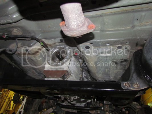
I reshaped the oil cooler lines from the auto to fit the new locations on the manual. When I tried to hook them up I found they were 5/16" tube, and the manual took 3/8". The original lines went to 3/8" at the radiator so I made new lines that went to the front.
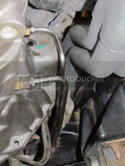
Oil cooler fittings. Auto on left, manual on right.
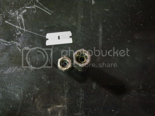
The ecu has three connectors. The one on the left goes to the auto transmission. I unplugged it and left it with the auto. There was one other connector for the auto near the ecu. There were two wires that needed to be connected for the starter to work, and two others that run the reverse lights. I still need to get a connector for the reverse switch.
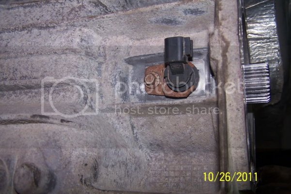
Also, I am still working on the connection for the vehicle speed sensor. There was on on the auto, and it looks like there may be one on the T/C. It seems to drive fine without it, except no speedo. I may try using a salvage ecu from an '03 F250 5.4 manual trans truck. I don't use ABS, and I may use a pulse generator from one of the hubs for the VSS.
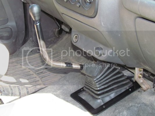
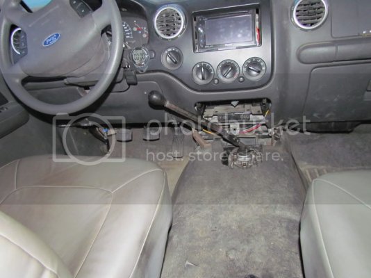
I will probably make a strangely curved shift lever to clear the cup holders, but here it is as it drives. I love having a manual tranny!
As far as I know, the only manual transmission that Ford used with the MOD 5.4 is the ZF 6 speed. Unfortunately, it is 4 3/16" longer than the auto and has a larger output shaft. I discovered this after I started taking things apart.
This is the output shaft on the auto.

I could have used a transfer case from an F250, but I wanted the all-wheel-drive and I figured I might as well stick with the electric transfer case shifter. I measured carefully and decided the extra length would not be a problem. The fuel tank looks like it was made for the longer tranny.
I called Moser Engineering to see if they could re-spline the 6-speed output on the main shaft to fit the Borg Warner T/C. The answer was "$65" so I disassembled the tranny and sent off the shaft. I disassembled the transfer case too and sent the input for matching. They said turnaround would be a couple of days.
Meanwhile I installed the clutch pedal and cut a hole in the floor for the shifter.
I had ordered a pedal assembly for an '03 F250. The brake master cylinder holes and an alignment pin lined up with the Expedition perfectly. There were two upper mounting bolt holes in the F150 pedal bracket that didn't have holes in the Expy. I scribed and drilled holes, then put access holes next to them for the clip nuts. It was a cramped and nasty job. I removed the steering column to do it.

My Expy had electrically adjustable pedals. I could have made a heroic effort and saved that feature, but I ditched it.
Pedal assemblies side by side.

The peg for the master cylinder rod on the brake pedal was too high. I relocated it. The clutch slave cylinder arm on the right side of the pedal assembly interfered slightly with the steering column, so I ground the arm for clearance.
The clutch slave cylinder location had a rubber plug in the firewall, and mounting holes for the reservoir. It went right in. The hydraulic line I got for an F150 had the wrong lower end for the F250 6-speed. The F250 has the clutch master to the left of the brake master. The F150/Expy is on the right. The stock lines are hard plastic so they don't re-shape very well. I got fittings and a line from Summit Racing. Russell 641001 and Aeroquip FPBA0049-36.

Doing the layout for the hole.

Cut out. I used the empty transmission housing to check the location. It was nice and light. The 6-speed weighs 240 pounds assembled.

From the bottom.

I installed a real flywheel and the clutch.

The fuel lines needed to be moved because the 6-speed is taller and wider at the top. I bent the return line in place, but had to remove the feed line and heat it to bend it without crimping.

Meanwhile, the mainshaft came back. Here's the re-spline.

Here's the gear cluster going back together.

Here's the tranny and transfer case all put back together and stacked.

I needed to relocate the transmission cross member back about a foot. I cut the original mounts off.


The original cross member was not long enough and too tall for the 6-speed. I used a piece of 1/8' wall 2" x 4" rectangular tubing for a cross member. It fit the mounts I had cut off. I trimmed the mounts to fit and welded them back on.
6-speed installed!

I reshaped the oil cooler lines from the auto to fit the new locations on the manual. When I tried to hook them up I found they were 5/16" tube, and the manual took 3/8". The original lines went to 3/8" at the radiator so I made new lines that went to the front.

Oil cooler fittings. Auto on left, manual on right.

The ecu has three connectors. The one on the left goes to the auto transmission. I unplugged it and left it with the auto. There was one other connector for the auto near the ecu. There were two wires that needed to be connected for the starter to work, and two others that run the reverse lights. I still need to get a connector for the reverse switch.
Also, I am still working on the connection for the vehicle speed sensor. There was on on the auto, and it looks like there may be one on the T/C. It seems to drive fine without it, except no speedo. I may try using a salvage ecu from an '03 F250 5.4 manual trans truck. I don't use ABS, and I may use a pulse generator from one of the hubs for the VSS.
I will probably make a strangely curved shift lever to clear the cup holders, but here it is as it drives. I love having a manual tranny!


