Heated Steering Wheel - Installation on my 2017

Disclaimer: Links on this page pointing to Amazon, eBay and other sites may include affiliate code. If you click them and make a purchase, we may earn a small commission.

OP
OP
17LimitedExpy

17LimitedExpy

Full Access Members
Joined
Jan 4, 2018
Posts
418
Reaction score
192
Location
TN
You are now ready to begin the process for routing the wire harness and making the splice connections required to connect the harness to the MS +/- CAN network and to a power source.

Note: The power source should only be one that is powered when the vehicle is On or in Accessory mode...highly recommend you don't connect to a power source that is on all the time, your battery won't like it for long (dead battery if you leave the HSW on).
 
OP
OP
17LimitedExpy

17LimitedExpy

Full Access Members
Joined
Jan 4, 2018
Posts
418
Reaction score
192
Location
TN
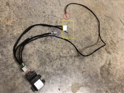
Strip back the black wrap on the wires going to the MS CAN network connector (circled in blue). NOTE: If you purchase/tell Lucas this wire harness is for the Expedition, you won't have this connector but in place you will have two wires labeled for MS + and MS -.

Wiring Harness Description.jpg

It may help if you plug in the connector to the HSW Module (see arrow in pic)...this may make it slightly easier to see/place where the wiring harness will run.
 
OP
OP
17LimitedExpy

17LimitedExpy

Full Access Members
Joined
Jan 4, 2018
Posts
418
Reaction score
192
Location
TN
Connection to the MS CAN Network is required so that you can integrate the Heated Steering Wheel into the modules required to control the HSW function.

To make it easier to connect the wire harness to the MS +/- Network, I removed the two screws holding the OBD connector under the dash. See pic below:
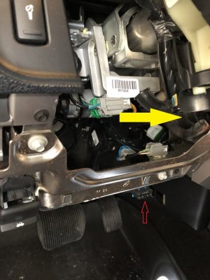
Where to place HSW Module.jpg

The OBD connector is on the bottom of the dash, just above your right leg when you are pushing on the brake. See Red Arrow.

Pull the OBD connector down to make it easier to access the connector and strip back the insulation wrap on the back side of the connector.

Yellow arrow points to the area where I placed the HSW module and zip tied it up out of the way. Recommend you wait to zip tie the HSW Module until all your connections/splices are made and you are ready to begin putting everything back together...this will give you a little flexibility to move the wire harness/HSWM slightly when making the connections.

NOTE: ensure you place the module in an area that won't affect/impact your steering wheel tilt/extend functions.
 
Last edited:
OP
OP
17LimitedExpy

17LimitedExpy

Full Access Members
Joined
Jan 4, 2018
Posts
418
Reaction score
192
Location
TN
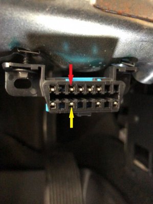
Pin 3 (red arrow) on the OBD connector is the MS Can + connection...it's a Gray & Orange wire.

Pin 11 (yellow arrow) on the OBD connector is the MS Can - connection...it's a Violet & Orange wire.

OBD Connector - Pin Locations.jpg

Once you locate the wires, use your splice connectors to secure the 2 wires from your wire harness to the respective MS + or - wires at the back of the OBD connector.

If you want, rewrap the insulation onto the wire loom at the back of the OBD connector. Install OBD connector to bottom of the dash with the two screws you removed.
 
Last edited:
OP
OP
17LimitedExpy

17LimitedExpy

Full Access Members
Joined
Jan 4, 2018
Posts
418
Reaction score
192
Location
TN
Once you have your wire harness spliced into the MS CAN Network, run the long power wire (red in pic) under the dash/across the bottom of the dash to the right/passenger side.

Wiring Harness Description.jpg
 
OP
OP
17LimitedExpy

17LimitedExpy

Full Access Members
Joined
Jan 4, 2018
Posts
418
Reaction score
192
Location
TN
I threaded the power wire through the area where the center console meets the dash...see pic below:

Power Wire Threading.jpg

I waited until I had the power wire connected to the power source before I zip-tied the wire in place behind the dash.
 
OP
OP
17LimitedExpy

17LimitedExpy

Full Access Members
Joined
Jan 4, 2018
Posts
418
Reaction score
192
Location
TN
Remove the kick panel at the lower right sight of the passenger foot well, it just pulls off:

Kick Panel.jpg
 
OP
OP
17LimitedExpy

17LimitedExpy

Full Access Members
Joined
Jan 4, 2018
Posts
418
Reaction score
192
Location
TN
You should now be able to see the Body Control Module (BCM) :

IMG_0480.jpg
 
OP
OP
17LimitedExpy

17LimitedExpy

Full Access Members
Joined
Jan 4, 2018
Posts
418
Reaction score
192
Location
TN
The power source I chose is hot when the Ignition is in Run or Accessory...when the vehicle is Off, there is no power to the HSW and no threat of draining the battery.

Here's the wire diagram I used to find my power source:

HSW-Power Diagram BCM.jpg

Pin 11 on Connector C2280F (see red arrow) is my power source.
 
Last edited:
Top