Door Sensor Data Error and Tire Pressure Monitor Error

Disclaimer: Links on this page pointing to Amazon, eBay and other sites may include affiliate code. If you click them and make a purchase, we may earn a small commission.

Skauber

Full Access Members
Joined
May 31, 2014
Posts
366
Reaction score
29
Location
Cagayan de Oro, Philippines
I'm pretty sure the VSM has to be reprogrammed since it has different configurations available like 4 or 5 TPMS sensors and probably other things depending on the trim level. I also think it has to be programmed to the VIN in order to accept communication from the PCM, but I can't say for sure.

If you don't have a Ford VCM (clone or OEM) available and the know-how, I would think the only option you have is to take it to a dealership and explain them the tests you've done, ask them to verify that the VSM is indeed dead or not (could be a power supply issue which has the be diagnosed properly), and then replace the VSM if it is indeed dead.
 

bobbyd38

Member
Joined
Jul 15, 2015
Posts
7
Reaction score
0
Location
MA
Did you ever resolve this? I'm having the EXACT same issue?

Thanks,
Bob
 
OP
OP
A

AcesOverEights

Full Access Members
Joined
Aug 7, 2013
Posts
94
Reaction score
11
Location
MN
Nope. Not yet. I have a service manual coming either today or tomorrow. I suspect that it is the splice on the medium speed canbus line that branches off into the TPMS section and Door Sensor/RKE section of the VSM. I am hoping that I can find the splice in the manual and then hoping the manual tells me where the splice is.

I'm getting to know alot more about the VSM and general CANBUS systems than I ever thought I would!

When I fix it I will let everyone know what the problem was and how to fix it.
 
OP
OP
A

AcesOverEights

Full Access Members
Joined
Aug 7, 2013
Posts
94
Reaction score
11
Location
MN
update:


FIXED!!!!


So. The service manuals are a life saver.
I was probing the wires that run to the VSM, 4 of them if I remember correctly. 3 of them had power. One did not. That was my starting point. It was the one that fed fuse #F1.5. (#F1.5 is #5 on the fuse panel cover)

The fuse tested good with the multimeter, so it ruled out a dead fuse. I probed the exposed ends of the fuse, with it in the fuse block (the manual calls it the Central Junction Box or CJB) and I had no power going to it. So, that circuit still looks like our culprit.

The wire feeding that fuse and that dead power wire on the VSM is a red wire with a white tracer. The manual says there is a splice on that wire between the VSM and the fuse. Good place to start looking. That splice exists under the passenger side sill plate, in the wire loom.

The splice is just to the front of the rear end of the loom, near the seat's front bolts, give or take. It has a shrink tube over the splice with some silicone goo sealing it up. I stripped that back, I saw some corrosion where the 2 RD/WHT wires connected to the single RD/WHT wire running to the rear. So I probed the junction. No power. It should have had power. So I probed each of the 2 wires individually. One had power, the other did not. So I inspected the "dead" wire. There was a break in the wire about 4" to the front of the truck from the splice. I probed ahead of the break, VOLTAGE!!!

The wire had broken for some reason. Maybe it was corroded and broke, maybe it was already partially broken from the factory. Who Knows. Doesnt matter.
I soldered a new patch wire between the 2 forward wires and the one rear wire. Fired the truck up, no errors. Door locks worked. Keyless worked.


tl:dr
Red wire with a white tracer had broken just ahead of the splice in the passenger side sill plate. Repaired said wire. Truck is back to functional.
 
OP
OP
A

AcesOverEights

Full Access Members
Joined
Aug 7, 2013
Posts
94
Reaction score
11
Location
MN
Thanks. I wasnt to keen on the idea of blindly dumping money at a new VSM. I doubt the dealership would have spent the time properly diagnosing it, they would have just threw in a new VSM and charged me a boat load for it and still not resolved the problem.

I can get pics of the after. As long as no one laughs at the fact I used an incorrect color jumper wire and my lack of proper shrink tubing. I think I might have a picture of the before as well. I took some pics when I was chasing down that splice in a different area.
 

Skauber

Full Access Members
Joined
May 31, 2014
Posts
366
Reaction score
29
Location
Cagayan de Oro, Philippines
I don't think the electrons care what color the wire is. :) A correct splice should be sealed with proper heat shrink, but as long as it works and it's properly insulated then it does the trick.
 
OP
OP
A

AcesOverEights

Full Access Members
Joined
Aug 7, 2013
Posts
94
Reaction score
11
Location
MN
Yeah. Its a healthy wrap of electrical tape. I wanted it fixed ASAP as I needed the truck today and didnt have any real shrink tube on hand. It will be easy to unwrap, unsolder and shrink tube properly. But thats a job for the weekend with a beer in hand.


Here are a couple pics.
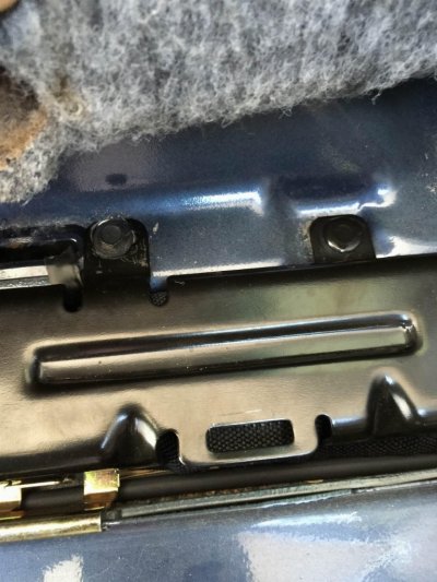
This is a pic of the general area the splice exists. After you remove the passenger side sill plate, this metal cover is what you will see. The splice is inside the wire loom below this, approximately between the bolt on the left side of the pic and the alignment pin towards the right side. Thats the vague area

QJae3ZV.jpg
Click if the image doesnt load


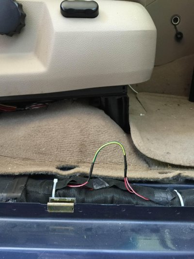
Here is a pic of the actual wires after being repaired. I'll redo the shrink tubing later. For now it works. Note the 2 RD/WHT wires running to the front of the truck and 1 towards the rear. One of the wires heading to the front carries power from the fuse block, the other runs to the VSM, the one to the rear goes to the rear power seats.

NQr7V3u.jpg
Click if the image doesnt load

I have a couple more pics at home on the real camera, I'll look them over and see if I have anything that pertains to this. Otherwise These are pretty close.
 
Last edited:

Latest posts

Forum statistics

Threads
53,730
Posts
503,303
Members
47,395
Latest member
Jefes_Shyt
Top