Speed Control
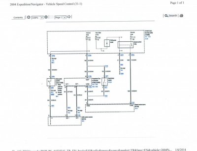
The speed control system consists of the following components:
- brake pedal position (BPP) switch
- deactivator switch
- speed control actuator
- speed control actuator cable
- speed control actuator switches
- powertrain control module (PCM)
Principles of Operation
The speed control system is designed to maintain a selected vehicle speed between approximately 40 and 200 km/h (25 and 125 mph).
The electronic stepper motor (internal to the speed control actuator) is controlled by turning the three phases of the motor on and off in sequence. The sequence determines the motor direction (open throttle or closed throttle based on vehicle speed).
The speed control module is fully integrated into the powertrain control module (PCM). The PCM strategy uses engine control to accelerate smoothly. In instances where the vehicle tends to want to exceed the set speed, the PCM will invoke an engine braking strategy to help maintain the desired vehicle speed.
Whenever the system is engaged and active, a speed control set indicator will be illuminated in the instrument cluster.
The brake pedal position (BPP) switch is a normally open switch. When the brake pedal is applied with the speed control system engaged, the BPP switch closes to battery voltage, putting the vehicle speed control in stand-by mode.
NOTE: The deactivator switch is provided as an additional safety feature.
Normally, when the brake pedal is pressed, the PCM will deactivate the speed control system. Under increased brake pedal effort, the deactivator switch, a normally closed switch, will open and remove power to the speed control actuator clutch, releasing the throttle independently of the PCM.
The clockspring provides the electrical interface between the steering column wiring and the speed control switches in the steering wheel.
The PCM sends a standard corporate protocol (SCP) output message to the instrument cluster to indicate when the vehicle speed control system is active.


