Not so Good Vibrations

Disclaimer: Links on this page pointing to Amazon, eBay and other sites may include affiliate code. If you click them and make a purchase, we may earn a small commission.

OP
OP
whtbronco

whtbronco

Full Access Members
Joined
Nov 13, 2021
Posts
443
Reaction score
199
Location
Winchester, VA
Almost done with input and rear output shaft disassembly.
 

Attachments

  • Planetary - front input shaft view.jpg
    Planetary - front input shaft view.jpg
    141.4 KB · Views: 0
  • Output shaft disassembly - front 1.jpg
    Output shaft disassembly - front 1.jpg
    206.7 KB · Views: 0
  • Output shaft disassembly - front 2.jpg
    Output shaft disassembly - front 2.jpg
    133.4 KB · Views: 0
  • Output shaft - front.jpg
    Output shaft - front.jpg
    214.1 KB · Views: 0
  • Case halves - inside empty.jpg
    Case halves - inside empty.jpg
    229.3 KB · Views: 0
OP
OP
whtbronco

whtbronco

Full Access Members
Joined
Nov 13, 2021
Posts
443
Reaction score
199
Location
Winchester, VA
Just 9 more pics.
 

Attachments

  • Rear output shaft bearing.jpg
    Rear output shaft bearing.jpg
    127.1 KB · Views: 0
  • Case half - front seals removed.jpg
    Case half - front seals removed.jpg
    290.9 KB · Views: 0
  • Front output shaft bearing removed.jpg
    Front output shaft bearing removed.jpg
    248.1 KB · Views: 1
  • Case half - front bearings removed.jpg
    Case half - front bearings removed.jpg
    248.3 KB · Views: 1
  • Case half - rear with bearing removed.jpg
    Case half - rear with bearing removed.jpg
    267.3 KB · Views: 1
OP
OP
whtbronco

whtbronco

Full Access Members
Joined
Nov 13, 2021
Posts
443
Reaction score
199
Location
Winchester, VA
Last one.

I tried to include the tool I used to remove the seals and bearings. For the snap rings I just used snap rings pliers and flat head screwdrivers. The damper requires a 13mm socket, the shift motor requires a 10mm socket. The shift motor connector I needed to depress the retaining clip and then use a flat head screwdriver to gently pry the halves apart. The case bolts are T-40. The nuts for the coil are also 10mm, don't forget to push the coil wire in a bit before separating the case halves.
 

Attachments

  • Shift shaft seal removed.jpg
    Shift shaft seal removed.jpg
    247.2 KB · Views: 1
  • BW4416 parts laid out.jpg
    BW4416 parts laid out.jpg
    239.8 KB · Views: 1
  • Planetary bearings - factory on R - lesser quality replacement on L.jpg
    Planetary bearings - factory on R - lesser quality replacement on L.jpg
    158.9 KB · Views: 1
  • Planetary with bearing removed.jpg
    Planetary with bearing removed.jpg
    167.3 KB · Views: 1
OP
OP
whtbronco

whtbronco

Full Access Members
Joined
Nov 13, 2021
Posts
443
Reaction score
199
Location
Winchester, VA
I am wondering about the condition of the clutch pack, but the one clutch plate that's visible looks serviceable. There are still visible, consistent depth grooves. The orange coating is flaking off a bit though. The other thing that concerns me is that the thrust bearing that sits in front of the output shaft chain sprocket only had 1 washer, I'm accustomed to seeing 1 on each side of them and the only replacement I have found shows 2 washers.

My current plan is to reassemble the salvage yard transfer case tomorrow and then swap them next weekend. I'm open the factory transfer case whether I decide to rebuild it now or not, I need to know what's wrong inside.
 
OP
OP
whtbronco

whtbronco

Full Access Members
Joined
Nov 13, 2021
Posts
443
Reaction score
199
Location
Winchester, VA
The USA Standard Gear ZTBK4416 bearing and seal kit seems okay, but not great. The front output shaft seal does not match the picture of the kit, the factory seal or the other available aftermarket seals. The input shaft seal and the front output shaft seal in the kit are identical. All others have a lip that sticks out about 5/16" and sits in a channel on the back of the front driveshaft pinion yoke. I'm not sure it's necessary, but it would help some to keep dirt away from the seal and shaft.

In the other attachment there's 2 seals on the left side and an o-ring top right. I cannot figure out where those go. I just went through everything and I don't see a place for them. The seal in the lower right is for the shift shaft. Maybe there are slight differences in the 2005/06 transfer cases that use these I don't know.

As noted in a previous attachment the bearing that goes inside the planetary has fewer roller needles than the factory bearing. At least they are tight, the factory ones are very loose and a few nearly fall out of the cage.

1710019731095.png
1710018997712.png
 
OP
OP
whtbronco

whtbronco

Full Access Members
Joined
Nov 13, 2021
Posts
443
Reaction score
199
Location
Winchester, VA
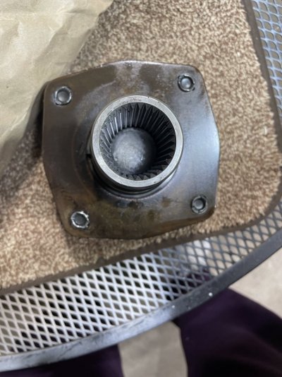
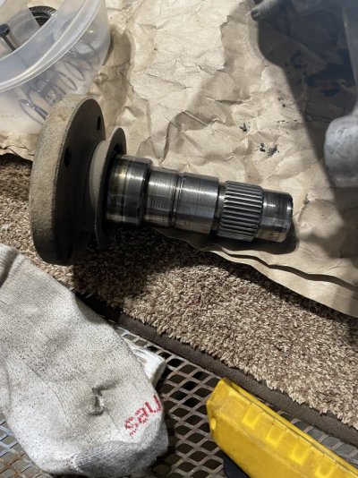
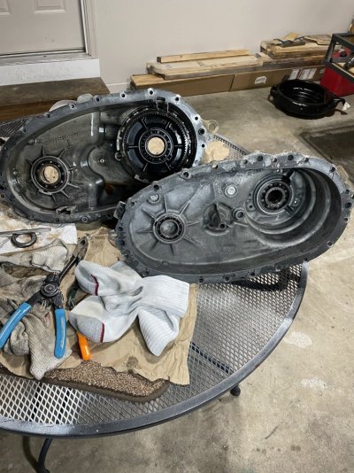
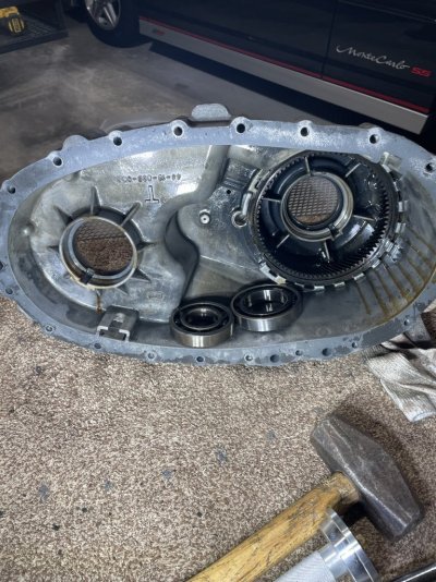
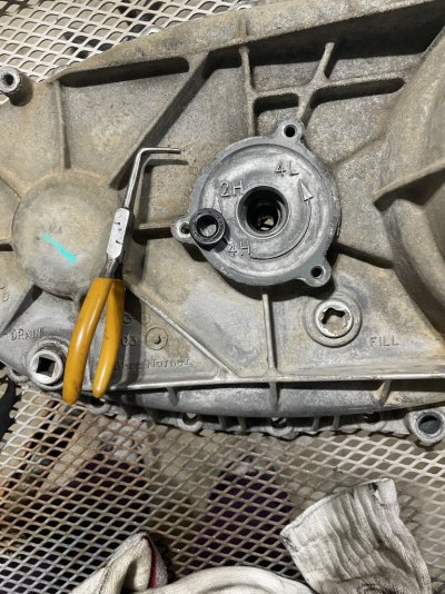
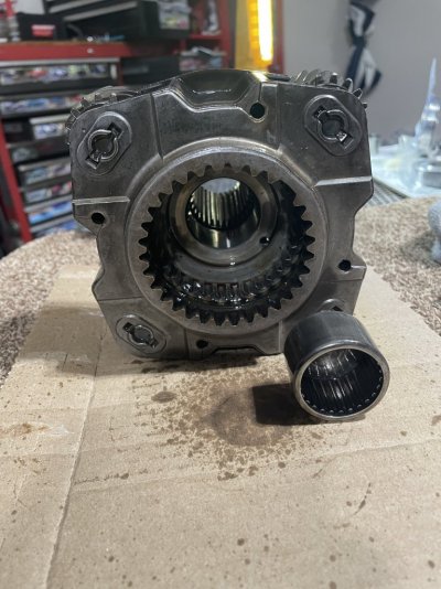
I have finished the reassembly of the salvage yard transfer case. It turns pretty easy, easier now than prior to disassembly. Without much effort I can turn the front output and hold the input still. The input shaft was coated in ATF too. The only noise when turning it by hand I believe is from the chain. It has a new Motorcraft shift motor on it.

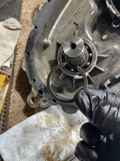
It took 7.5hrs to reassemble and clean up, dang I'm slow. Due to the snow squalls I moved my neighbors 20-ton press to my garage and had to put it back of course. I made a run to the parts store for the proper style front output seal and took a break for dinner. I also kept second guessing myself and decided several parts needed to be cleaned before being installed which all took additional time. Oh and on Friday I had used dish detergent and water to clean up the mostly empty case halves. There was still water between the sun gear and the case so it had to come out, turned out to be a good thing as there were a couple spots of light rust that had formed in the teeth. That ~6" snap ring is strong, but using 2 flat head screwdrivers I was able to work my way around with 1 underneath it to keep up ward pressure on it and the other to push in and out of the retention groove.

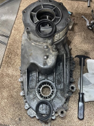
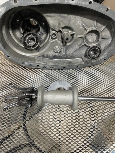
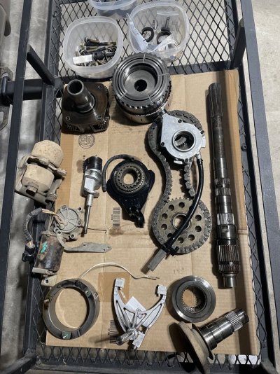
A couple things I learned. Turning the rear output shaft while installing some parts makes it much easier. For the 4Lo hub it helped, for the pump there's no way to install it without turning the shaft while holding a bit of pressure on it and waiting 'til it lines up just right. Holding the clutch pack and spring down while putting a snap ring back is slightly tricky. I ended up getting the snap ring right above the assembly, then holding it all compressed and tapping the snap right down with a flat head screwdriver. Hands down the most difficult part of the entire thing was getting the shift fork shaft lined up while installing the rear case half. It always leaned over towards the output shaft, the shift forks rest on it and cause this. I test fit the case halves, you need to line up the shift fork spring on the rear case half as you're seating it. It took ~10 more minutes to get the shift fork shaft lined up and the case halves fully seated, but I got it with a long screwdriver. I put some silicone on it to seal the case halves and fought with it for ~20 minutes this time. The chain is in the way to go straight in to the shaft and you can't angle the rear case half at all as both output shafts are in their bearings and the shift motor shaft is also seated a good bit before the shift fork shaft is against the rear case halve.

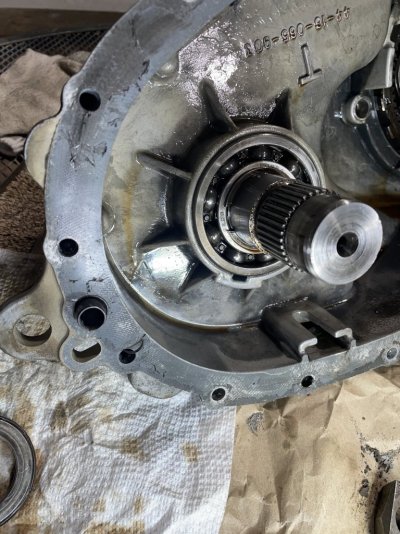
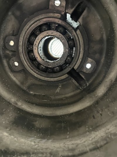
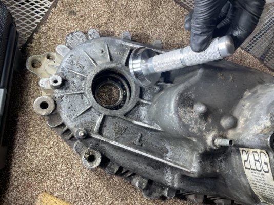
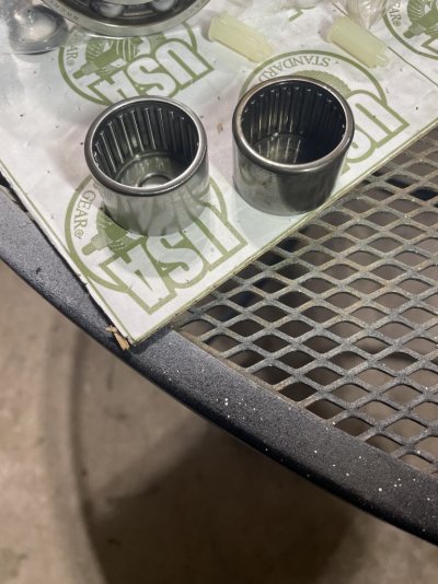
A 20-ton press is overkill for this. The bearing inside the planetary took the most pressure to seat by far, but it took the most to remove as well. The planetary is steel, the case halves for the other bearing seats are aluminum. The rear bearing for the front output shaft was also pressed in. For the other 3 I ultimately found it was just too hard to use the press and used my hand held bearing/seal installer with my mini sledge. Reconfiguring the press for each bearing is time consuming, but I tried for all 5 bearings. The rear bearing for the rear output shaft I could not find bits and pieces to line it properly so the hand held was the only option here with my available tools.

I poured a 1/3qt of ATF LV in an old plastic food container to soak parts and make it easy to get a few drops of ATF to drip in places needed during assembly. I poured what was left into the clutch assembly before closing it up.

I feel good about the current state of the salvage yard transfer case. I'm gonna have to give my body several days to recover. I plan to swap the transfer cases next Saturday.

EDIT: I never did find where those 3 seals/o-rings could be used.
 
Last edited:
OP
OP
whtbronco

whtbronco

Full Access Members
Joined
Nov 13, 2021
Posts
443
Reaction score
199
Location
Winchester, VA
I also found the other thrust washer bearing. 3rd times the charm shall we say. I found it stuck to the chain sprocket, but I didn't see it there previously for some reason.
 
OP
OP
whtbronco

whtbronco

Full Access Members
Joined
Nov 13, 2021
Posts
443
Reaction score
199
Location
Winchester, VA
This document was also very helpful during the reassembly.
 

Attachments

  • Exploded view.jpg
    Exploded view.jpg
    191.3 KB · Views: 2
OP
OP
whtbronco

whtbronco

Full Access Members
Joined
Nov 13, 2021
Posts
443
Reaction score
199
Location
Winchester, VA
Last night I cleaned the damper that came with my salvage yard transfer case. It was so nasty even if I don’t use it I don’t want to put it away so filthy. This morning I took some measurements preparing for the transfer case swap to see how much clearance I have right now, 11.5” to the frame. I’m trying to decide if I want to try a transmission jack again, or make a wooden platform for my floor jack. I have had truly terrible results with transfer cases on transmission jacks, they just don’t sit flat like a transmission does. Last time I put the transfer case in my wife just bench pressed it and I pushed it on the transmission.

Anyway, I noticed that there was no damper on my transfer case, LOL. Where the heck did it go and when. So I put the now clean damper on and went on a 90 mile trip, it does actually help a bit. It nearly eliminated the vibration under power, but did little for the coasting vibration. I guess since it’s kinda like a wart on the transfer case and not common based on my previous trucks I reckon I just didn’t notice it was missing.

If you’re sitting there laughing and saying “you’re an idiot” it’s all good. I did the same thing, haha.
 
OP
OP
whtbronco

whtbronco

Full Access Members
Joined
Nov 13, 2021
Posts
443
Reaction score
199
Location
Winchester, VA
Since it takes me time to do things I got the truck up on ramps front and jack stands rear this evening. The rear driveshaft is out, connector removed, ATF drained, front driveshaft shield removed and damper removed. I made platform for my jack as well and that needed a couple quick mods as well. I'm ready to swap the transfer cases tomorrow with my beautiful wife helping.

The reason for this post though is that I have confirmed my suspicion about the front output shaft bearings being worn out. With the front driveshaft shield removed I was able to grab the output flange firmly and easily move it side to side. I always like to get confirmation that I made the right decision, sometimes I certainly do not.
 

Latest posts

Forum statistics

Threads
53,584
Posts
502,193
Members
47,159
Latest member
tifanydire
Top