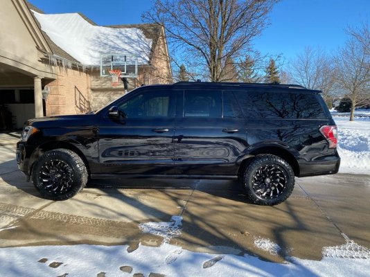
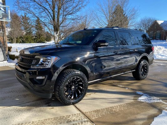
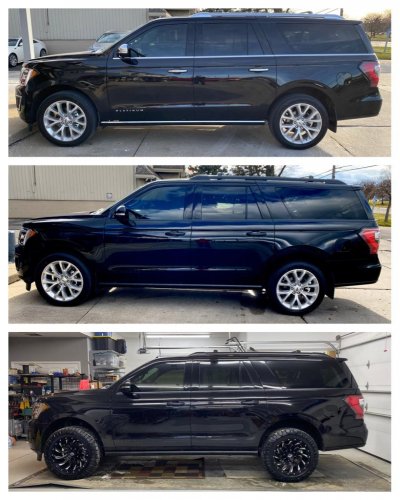
Ready Lift 3-2 kit installed with CCD suspension

Disclaimer: Links on this page pointing to Amazon, eBay and other sites may include affiliate code. If you click them and make a purchase, we may earn a small commission.

Lou Hamilton

Full Access Members
Joined
Nov 28, 2019
Posts
939
Reaction score
633
Location
Maryland
Yessir, the front and rear kit. As stated by another member here who just hooked up the stock CCD links, I really cannot tell the ride difference at all. Rides great. Also, the CCD wiring was plenty long to accommodate the struts being rotated, so the tech did not switch sides.

I also don't have the equipment, so my tire shop did it. It's not rocket science by any means. They charged me strut job labor, about $400. Fine with me!

That is the other thing. I need to find a shop that I can trust.

In the past, I got my tires from a truck shop... and by truck shop, I mean commercial and big rig truck tire shop.

I know it is not rocket science, but I would like to find a shop that is at least familiar with the Expedition and its suspension. My Trick Truck custom shop has never touched an Expedition so they were hesitant to do anything other that swap tires and put a 10mm spacer to help prevent rubbing.
 

Dakota4ce

Full Access Members
Joined
May 2, 2018
Posts
119
Reaction score
70
Location
South Dakota
That is the other thing. I need to find a shop that I can trust.

In the past, I got my tires from a truck shop... and by truck shop, I mean commercial and big rig truck tire shop.

I know it is not rocket science, but I would like to find a shop that is at least familiar with the Expedition and its suspension. My Trick Truck custom shop has never touched an Expedition so they were hesitant to do anything other that swap tires and put a 10mm spacer to help prevent rubbing.

It is as easy as doing a strut change. More or less.
 

Dakota4ce

Full Access Members
Joined
May 2, 2018
Posts
119
Reaction score
70
Location
South Dakota
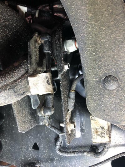
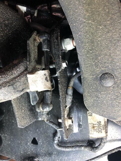
Do us a favor and take a picture of the ride height sensors with the truck up in the air with the suspension hanging. I want to see the angle of the arm with stock links. They have to be getting close to end of travel.

I don't have a hoist, unfortunately. I suppose I could jack it up and grab some jack stands.
 

Dakota4ce

Full Access Members
Joined
May 2, 2018
Posts
119
Reaction score
70
Location
South Dakota
Do us a favor and take a picture of the ride height sensors with the truck up in the air with the suspension hanging. I want to see the angle of the arm with stock links. They have to be getting close to end of travel.

ef76d00497a9a989988a498447f3a591.jpg

I disconnected the linkage that doesn’t appear the sensor arm has a bottom limit. There is no positive stop moving down.

Isn’t it just a speed and amplitude of deflection measurement anyway? Like a potentiometer?

Forgive me, not an expert on this stuff by any stretch.


Sent from my iPhone using Tapatalk
 

Fozzy

Full Access Members
Joined
Sep 5, 2019
Posts
1,200
Reaction score
1,159
Location
Riverton
There is plenty of physical travel. They move over 180 degrees. The question is how much of it is data logged. If you watch the Fusion pothole video the sensor detects the wheel falling into the pothole and increases the rebound dampening keeping the tire from going all the way into the pothole. This smooths out the ride. The sensors do not act like a bypass shock. Meaning there is no set position directly related to the dampening or rebound characteristics of the shock and its shaft position.


Sent from my iPhone using Tapatalk
 

Dakota4ce

Full Access Members
Joined
May 2, 2018
Posts
119
Reaction score
70
Location
South Dakota
There is plenty of physical travel. They move over 180 degrees. The question is how much of it is data logged. If you watch the Fusion pothole video the sensor detects the wheel falling into the pothole and increases the rebound dampening keeping the tire from going all the way into the pothole. This smooths out the ride. The sensors do not act like a bypass shock. Meaning there is no set position directly related to the dampening or rebound characteristics of the shock and its shaft position.


Sent from my iPhone using Tapatalk

As of a couple hundred miles this weekend, I cannot sense any sort of change. But I am all ears if someone finds otherwise...I would think the major parameters are speed and amplitude and if it senses large values in either, the computer makes the change.

Certainly not opposed to adjustable linkages, just not sure in this case they're needed. I do know of other vehicles where this would certainly result in drastic ride quality changes.
 

Miekk

Full Access Members
Joined
Jan 9, 2012
Posts
156
Reaction score
32
Location
Madison Lake, MN
ef76d00497a9a989988a498447f3a591.jpg

I disconnected the linkage that doesn’t appear the sensor arm has a bottom limit. There is no positive stop moving down.

Isn’t it just a speed and amplitude of deflection measurement anyway? Like a potentiometer?

You are correct, there is no positive stop. However they are designed to be at a 90° TT angle or three or 9 o’clock positions. The closer you get the sensor arm in line with the link, the more sporadic the movements going to be, sending quick data changes to your computer for readings.

I make the censor links adjustable mainly because I started out building these or we are bagged expeditions. If these only need to be a new length and the truck doesn’t care where zero is, I can certainly build them solid which would save everybody some $.
 

Dakota4ce

Full Access Members
Joined
May 2, 2018
Posts
119
Reaction score
70
Location
South Dakota
You are correct, there is no positive stop. However they are designed to be at a 90° TT angle or three or 9 o’clock positions. The closer you get the sensor arm in line with the link, the more sporadic the movements going to be, sending quick data changes to your computer for readings.

I make the censor links adjustable mainly because I started out building these or we are bagged expeditions. If these only need to be a new length and the truck doesn’t care where zero is, I can certainly build them solid which would save everybody some $.

On the front sensor as pictured, the arm cannot physically get to 90 degrees (9 o'clock). It hits its own mounting bracket before it can get to that position...like appears to be well short of able to hit 9 o'clock. How does that figure into this, if at all?
 

Miekk

Full Access Members
Joined
Jan 9, 2012
Posts
156
Reaction score
32
Location
Madison Lake, MN
On the front sensor as pictured, the arm cannot physically get to 90 degrees (9 o'clock). It hits its own mounting bracket before it can get to that position...like appears to be well short of able to hit 9 o'clock. How does that figure into this, if at all?
The farther you get from 90°, the quicker more sporadic the reading change is going to be back to the computer. It’s as if you were going from a bumpy road to a washboard road.
All I’m trying to do is get the sensors back to the original engineered factory design operating location and range.
You certainly might get by cheating it, just remember; you can cheat on your wife too, but it’s not recommended and typically has a consequence or two....:D
 
Top