
Gregg Eshelman
Full Access Members
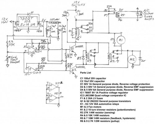
For vehicles with only a mechanical fan, I have a schematic and parts list for a DIY dual fan controller that first turns them on in series so each is running half speed on 6 volts, then if the temp gets hot enough it switches the fans to parallel so they run at full speed at 12 volts. Both temperature points are adjustable. It also has an input to connect to the AC clutch to turn the fans on in series mode when the air conditioning is turned on. If the temp goes to the high setting the fans will still switch to parallel mode.
I found that some Pugeot cars had a setup like this and a friend drew the schematic. He was a US Navy radioman, from back when they had to know how to build the equipment. Died from mesothelioma, likely from asbestos dust breathed in crawling around the innards of Navy ships.
Parts List
C1 100uf 35V capacitor
C2 10uf 35V capacitor
D1 50V 1A General purpose diode, Reverse voltage protection
D2 & 3 50V 1A General purpose diode, Reverse EMF suppression
D4 & 5 50V 6A General purpose diode, Reverse EMF suppression
IC1 7808T 8V 1A Positive voltage regulator
IC2 LM339M Quad voltage comparator IC
F1 & 2 30A LV fuses
Q1 & Q2 2N2222 General purpose transistors
K1 - K4 12V 30A automotive relays
M1 & 2 Fan motors
R1 & 2 10 turn trimmer resistors (potentiometers)
R3 27K 1/4W resistor (sensing)
R4 & 8 10K 1/4W resistors
R5 & 7 10M 1/4W resistors (feedback, hysteresis)
R6 & 9 2.7K 1/2W resistors (pullup)
The dual version of the LM339M can be used instead. The author of this schematic simply didn't have any duals on hand. What can be done with the quad chip is instead of tying all the unused pins together, a duplicate of the circuit can be built using the other half of the chip, to series/parallel control two more fans, plus an input to force them on in series mode.
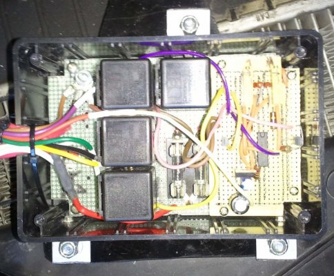
DURAKOOL - DZ85AB-5-PCB - Automotive Relay Socket
Four 12V "Ice Cube" relays, rated for high temperature. (The ones in the image are not high-temp, they failed.)
Next three are different sources for the sensor connector.
Ford WPT437
Airtex / Wells 1P1095
STANDARD MOTOR PRODUCTS S-612 connector TX6 sensor
Santech Industries, Inc. MT0488 sensor
Ready Aire 36407 sensor
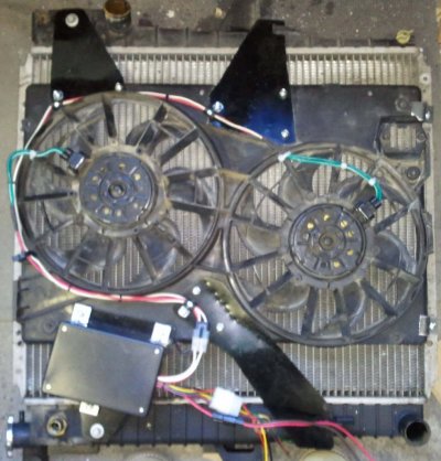
I do not remember what Ford these fans are from. They're mounted vertically on a 1997 Mountaineer radiator, using the original fan shroud mountings. It took a long time to find a non-ripoff source for the fan power connectors. It's not in the documentation I saved on this project. IIRC they cost $12 to $15 each where I bought them when every other source wanted $30 to $40 each. Always get the connectors with a lot of wire when you buy cooling fans.
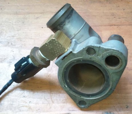
For the sensor there was a ready made spot to drill and tap pipe threads in the top of the thermostat housing. The 90 degree brass elbow was needed for clearing something above, probably the ignition coils.
The reason the control is assembled on a piece of perfboard, a small protoboard, and lots of point to point wiring is Radio Shack had replaced all their decades old line of project boxes, but *didn't update* any of their prototyping PCBs to fit the new boxes. It's no wonder they went out of business when they couldn't even manage such a simple feat of common sense.
I found that some Pugeot cars had a setup like this and a friend drew the schematic. He was a US Navy radioman, from back when they had to know how to build the equipment. Died from mesothelioma, likely from asbestos dust breathed in crawling around the innards of Navy ships.
Parts List
C1 100uf 35V capacitor
C2 10uf 35V capacitor
D1 50V 1A General purpose diode, Reverse voltage protection
D2 & 3 50V 1A General purpose diode, Reverse EMF suppression
D4 & 5 50V 6A General purpose diode, Reverse EMF suppression
IC1 7808T 8V 1A Positive voltage regulator
IC2 LM339M Quad voltage comparator IC
F1 & 2 30A LV fuses
Q1 & Q2 2N2222 General purpose transistors
K1 - K4 12V 30A automotive relays
M1 & 2 Fan motors
R1 & 2 10 turn trimmer resistors (potentiometers)
R3 27K 1/4W resistor (sensing)
R4 & 8 10K 1/4W resistors
R5 & 7 10M 1/4W resistors (feedback, hysteresis)
R6 & 9 2.7K 1/2W resistors (pullup)
The dual version of the LM339M can be used instead. The author of this schematic simply didn't have any duals on hand. What can be done with the quad chip is instead of tying all the unused pins together, a duplicate of the circuit can be built using the other half of the chip, to series/parallel control two more fans, plus an input to force them on in series mode.
DURAKOOL - DZ85AB-5-PCB - Automotive Relay Socket
Four 12V "Ice Cube" relays, rated for high temperature. (The ones in the image are not high-temp, they failed.)
Next three are different sources for the sensor connector.
Ford WPT437
Airtex / Wells 1P1095
STANDARD MOTOR PRODUCTS S-612 connector TX6 sensor
Santech Industries, Inc. MT0488 sensor
Ready Aire 36407 sensor
I do not remember what Ford these fans are from. They're mounted vertically on a 1997 Mountaineer radiator, using the original fan shroud mountings. It took a long time to find a non-ripoff source for the fan power connectors. It's not in the documentation I saved on this project. IIRC they cost $12 to $15 each where I bought them when every other source wanted $30 to $40 each. Always get the connectors with a lot of wire when you buy cooling fans.
For the sensor there was a ready made spot to drill and tap pipe threads in the top of the thermostat housing. The 90 degree brass elbow was needed for clearing something above, probably the ignition coils.
The reason the control is assembled on a piece of perfboard, a small protoboard, and lots of point to point wiring is Radio Shack had replaced all their decades old line of project boxes, but *didn't update* any of their prototyping PCBs to fit the new boxes. It's no wonder they went out of business when they couldn't even manage such a simple feat of common sense.