Help Installing Alarm/Remote Start in 97 Expedition

Disclaimer: Links on this page pointing to Amazon, eBay and other sites may include affiliate code. If you click them and make a purchase, we may earn a small commission.

stamp11127

Full Access Members
Joined
Mar 10, 2012
Posts
6,218
Reaction score
1,250
Location
Temple, Georgia
Your going to need the wiring diagrams first to study, then to plan the "attack".
You want to know where your going to tap into the harness before jumping in. If you don't you'll end up with a mess.
Butt connectors, to me, are not the way to go. Strip, tin, solder then heat shrink is the only professional way to do this. Think about it, do you see any butt connectors in the factory harness?
I'll try to look at this tonight for you.

Have you looked at what the current system is and how the connections were made? If you can get the wiring schematic for it you can use it as a guide for some of the connections or if the connections are proper tie into that harness since the wires are already there. But if "Bubba" installed it with masking or duct tape I'd redo the entire setup.
 
Last edited:
OP
OP
M

mikescl11

Member
Joined
Mar 2, 2014
Posts
8
Reaction score
0
Location
my house
Your going to need the wiring diagrams first to study, then to plan the "attack".
You want to know where your going to tap into the harness before jumping in. If you don't you'll end up with a mess.
Butt connectors, to me, are not the way to go. Strip, tin, solder then heat shrink is the only professional way to do this. Think about it, do you see any butt connectors in the factory harness?
I'll try to look at this tonight for you.

Have you looked at what the current system is and how the connections were made? If you can get the wiring schematic for it you can use it as a guide for some of the connections or if the connections are proper tie into that harness since the wires are already there. But if "Bubba" installed it with masking or duct tape I'd redo the entire setup.

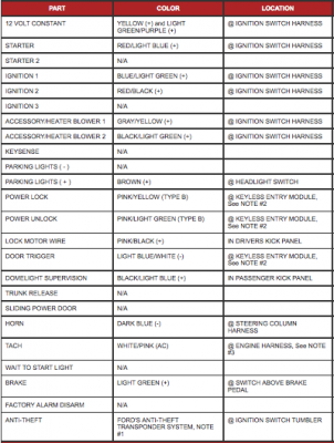
I have yet to check out the current remote start and connections because I don't want to have my dash ripped apart for a week, I'd like to get in there and get it all done at one time. Last week it was warm out and now tonight we are getting snow so I'm not sure how soon I will be able to get in there and look at the connections. Here is what I could find as far as the wires in my truck, hope this helps.

Thanks
Screen Shot 2014-03-23 at 3.09.11 PM.png
 

stamp11127

Full Access Members
Joined
Mar 10, 2012
Posts
6,218
Reaction score
1,250
Location
Temple, Georgia
I'm going to be an ass for a bit but I don't pay attention to those. I go by the factory wiring diagrams/books - for the reason I can see the circuit and it's logic, location of connectors, ground points etc. As posted earlier get the dvd on the wiring. I would expect at least 10 pages would cover what we need to look at.
Also i don't remember if the 97's have the GEM, you don't want to back feed on that.
 
Last edited:
OP
OP
M

mikescl11

Member
Joined
Mar 2, 2014
Posts
8
Reaction score
0
Location
my house
I'm going to be an ass for a bit but I don't pay attention to those. I go by the factory wiring diagrams/books - for the reason I can see the circuit and it's logic, location of connectors, ground points etc. As posted earlier get the dvd on the wiring. I would expect at least 10 pages would cover what we need to look at.
Also i don't remember if the 97's have the GEM, you don't want to back feed on that.


Alright, I will work on getting the dvd and get back too you once its here

Thanks
 
OP
OP
M

mikescl11

Member
Joined
Mar 2, 2014
Posts
8
Reaction score
0
Location
my house
I'm going to be an ass for a bit but I don't pay attention to those. I go by the factory wiring diagrams/books - for the reason I can see the circuit and it's logic, location of connectors, ground points etc. As posted earlier get the dvd on the wiring. I would expect at least 10 pages would cover what we need to look at.
Also i don't remember if the 97's have the GEM, you don't want to back feed on that.

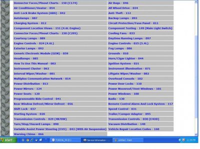
here are the diagrams i have to choose from. which ones do you need to help me install this system?

Thanks
diagrams.jpg
 

stamp11127

Full Access Members
Joined
Mar 10, 2012
Posts
6,218
Reaction score
1,250
Location
Temple, Georgia
I'll look at my discs sometime tomorow afternoon and let you know. It wouldn't hurt to start looking at the starting/charging circuit, power door locks and power distribution. Let us know how well you understand the diagrams so we can tailor the dialog accordingly.
 

stamp11127

Full Access Members
Joined
Mar 10, 2012
Posts
6,218
Reaction score
1,250
Location
Temple, Georgia
I've loaded my discs and have started reading the install manual. Two things are noted:

1) "Some vehicles have a factory installed transponder immobilizer system that can severely complicate the installation. There is a possibility that this system cannot be installed on some immobilizer-equipped vehicles." They don't specifically say Ford so we will see.

2) "Do not use conventional crimp lock, bullet on any wiring. Poor wiring, i.e. taped joints will possibly introduce unreliability into the alarm system and may result in false alarms or incorrect operation. We suggest soldering all connection points." - Soldering / heat shrink tubing is the only way to go.

How are your soldering skills? Do you have the correct tools for doing this - wire stripper(automatic type), dikes, soldering iron, 60/40 solder, heat gun?

If not, hold off on getting them until after it is determined that the system will work on Fords.

Things to consider:
1) Where are you going to mount the siren? Should be facing a direction so that it doesn't fill with water or gets blasted from road debris. Also keep in mind once the location is determined, where the wiring is going to be run.
2) Where are you placing the valet switch. Avoid a place that will be in the way if you need to remove any trim. You want ease of access but not in the way.
3) Location of LED status indicator - same considerations as #2
4) Shock sensor location - same considerations as #2

More to come - stay tuned....
 
Last edited:
OP
OP
M

mikescl11

Member
Joined
Mar 2, 2014
Posts
8
Reaction score
0
Location
my house
I've loaded my discs and have started reading the install manual. Two things are noted:

1) "Some vehicles have a factory installed transponder immobilizer system that can severely complicate the installation. There is a possibility that this system cannot be installed on some immobilizer-equipped vehicles." They don't specifically say Ford so we will see.

2) "Do not use conventional crimp lock, bullet on any wiring. Poor wiring, i.e. taped joints will possibly introduce unreliability into the alarm system and may result in false alarms or incorrect operation. We suggest soldering all connection points." - Soldering / heat shrink tubing is the only way to go.

How are your soldering skills? Do you have the correct tools for doing this - wire stripper(automatic type), dikes, soldering iron, 60/40 solder, heat gun?

If not, hold off on getting them until after it is determined that the system will work on Fords.

Things to consider:
1) Where are you going to mount the siren? Should be facing a direction so that it doesn't fill with water or gets blasted from road debris. Also keep in mind once the location is determined, where the wiring is going to be run.
2) Where are you placing the valet switch. Avoid a place that will be in the way if you need to remove any trim. You want ease of access but not in the way.
3) Location of LED status indicator - same considerations as #2
4) Shock sensor location - same considerations as #2

More to come - stay tuned....


This is the first time i have ever looked at a wiring diagram like these. That said, the more i study them the more i start to understand what i am looking at but as much detail that anyone can give me in helping install this thing would be great.
I have all of the tools to solder and am okay at it, just had planned to use the other connectors as the would be easier in the area to work in but starting to sound like ill be soldering everything. lol

1)siren is going under the hood somewhere, haven't figured out where yet but i will run the wire through the rubber grommet in the firewall.
2) & 3) are already installed and the wires are already ran under the dash to where i will keep the system.
4)i plan to put the sensor on the steering column


thanks
 

stamp11127

Full Access Members
Joined
Mar 10, 2012
Posts
6,218
Reaction score
1,250
Location
Temple, Georgia
At the front of the printed OEM service books there are pages that describe the various conventions used throughout the manual. Wouldn't hurt to familiarize yourself with those becore tearing into this. Just need to find them in the digital version.
 

Latest posts

Forum statistics

Threads
53,697
Posts
503,113
Members
47,346
Latest member
scoot701
Top