2003 Expy 5.4L - No start by ignition - Can start by jumpering relay in Distribution Block

Disclaimer: Links on this page pointing to Amazon, eBay and other sites may include affiliate code. If you click them and make a purchase, we may earn a small commission.

JunkyardDog

Member
Joined
Apr 18, 2015
Posts
17
Reaction score
2
Location
Cypress, TX
3 years after having another Distribution Block issue (https://www.expeditionforum.com/threads/power-distribution-relay-issue.26809/), I have a new issue. In late September, my daughter was using this vehicle at college (her car broke down and she borrowed this vehicle while I had her car, so I could work on it). She made a stop and when she returned it would not start. When in the RUN position, everything appeared normal. Twisting the ignition to start it and there was no crank at all. After 3 trips (@ 150 miles each), a funeral (longer story - a real funeral), and a 150 mile tow, I managed to get the right information to find a way to jumper the relay that was not working (I knew it would start if I could connect the right points). Due to everything else that has raining on my parade, I just now managed to get a look at it. I have been using my jumper to drive it everywhere. Otherwise, it runs fine and starts right up.

Since I had already pulled the distribution block out before, I knew I could fix it, if I could see the issue.

Well, I got it apart and all I find is another stressed trace. However, it is not open and it is not part of the starting circuit. I beefed up the trace like I did the other trace last time (The picture is the before beefing look.).

It is my understand of the following:

The relay in question (C2163 – Starter Relay) receives positive DC voltage from the ignition key (when turned to the START position), through the Neutral Safety Switch, via Pin 86, which is one side of the relay coil. Pin 85, the other side of the relay coil, is pulled low, via the computer, when all conditions to start are met (Alarm is disabled, etc.) When both of these conditions are met, the relay coil is energized; connecting Pin 30 to Pin 87. Pin 30 is connected to the Main Power Buss, and the Battery, power through Fuse 101 (30A). Pin 87 is connected to a 7/8 connector (I don't have any designations for these connectors. It happens to be the only connector that has 7 pins inserted for eight possible pin locationss.), on the back of the distribution panel.

Since I have been able to literally jumper the Pin 30 to Pin 87 manually to get it to start, those connections should be good. I do see 12 volts at Pin 86. Testing it with a test light, it can supply the low current to enable the relay.

My suspicion is that Pin 85 is not being pulled low enough, or at all. Whether it is the PCM or the wiring, I don't know yet. Right now, I am building a basic low power test light. I think a regular test light might draw too much current. Can anybody provide any insight to how I can BETTER test the PCM?
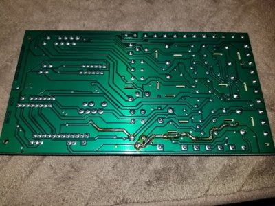
Distribution Block Back Side of Board 12-30-2018.jpg
 
OP
OP
J

JunkyardDog

Member
Joined
Apr 18, 2015
Posts
17
Reaction score
2
Location
Cypress, TX
I tested the starter relay circuit with my homemade test light. Instead of driving a relay when I turn the key, it drives my test light. Essentially, it is an LED with a series resistor and long test leads. In addition, there are connectors to allow adding a resistor across the LED and its series resistor. With my Multimeter in DC Current Mode in series of all of this, I measured ~15ma (correct for the values I chose). The relay would present a load of about 150ma. I added different value resistors until I reached the 200 ma point. Without knowing the limit of the PCM circuit, I am confident that it would be able to drive the relay.

So, in summary, I beefed up the exposed trace, I checked all connector, fuse, and relay contact points for issues and I find nothing else wrong. I also added quenching diodes to insure inductance feedback is not an issue. I reinstalled the fuse box and it starts right up using the ignition key, like there was never any problem.

I may have fixed the issue and may never know what I did to fix it. We'll see...
 
Last edited:

Trainmaster

Old School Member
Joined
Jun 17, 2017
Posts
3,402
Reaction score
1,925
Location
Rockaway Beach, NY
Great information Dog! Thanks for sharing. You know the drill: Wiggle the connectors and hope the contacts in the relays are good and not marginal and waiting to give you another problem.

Also check that water's not running into the connectors.

Good luck with this and hopefully it's fixed for good. Can you find a new board with new relays?
 

TobyU

Full Access Members
Joined
Apr 5, 2013
Posts
2,479
Reaction score
869
Location
Ohio
What are quenching diodes. It that like the one they will stick on mowers with electric PTO blade clutch at the relay area? I think they give a nice shock feedback when you dis-engage them.
Not all have these though. I assume it can hurt the relay??

All I ever really do with boards and ic stuff is fix or beef up whats obviously damaged/burned and replace any melted or blown out diodes or those little back 3 legged transistors? voltage regulators? or switching thingies??
 

Vancouver Bob

Full Access Members
Joined
Dec 22, 2016
Posts
719
Reaction score
355
Location
Vancouver, WA
Beefing up the traces worries me. The traces and circuit were designed to handle a certain amount of current. If traces are getting hot, there may be a high impedance short somewhere. You fix one problem but the issue will continue to move around as the next weakest link in the chain gets stressed, heated, melts, or something worse.
 

TobyU

Full Access Members
Joined
Apr 5, 2013
Posts
2,479
Reaction score
869
Location
Ohio
You can always fuse it. usually the weak link is the lousy small traces they expect to handle too much current. I see this a lot with limos. Everything is fine until they are 8-10 years old.
Then you have some connections that aren't flowing as they were. Some wiring that was barely big enough...no let's just say undersized to start with, grounds are not as good etc.
So resistance goes up and the weakest link can get hot hot hot.

You can always remove the circuit from the module if you want and put a a relay on the outside like on the common modules with 4-5 relays inside.
 
OP
OP
J

JunkyardDog

Member
Joined
Apr 18, 2015
Posts
17
Reaction score
2
Location
Cypress, TX
TobyU,
A quenching diode is another name for the diode that prevents the coil in the relay from releasing its AC voltage back into the circuit. This AC voltage is produced as the relay coil collapses when the DC voltage is removed. The original Ford relays have a resistor installed that performs nearly the same thing. I think their resistors dampen the AC more than block it. Additionally, the resistors draw current, when DC is present, where the diodes do not.

I have only replaced 1 relay; the PCM Power relay. I replaced it with a Bosch type relay. It does not have either a resistor or diode built in. So, I added the diode.

Vancouver Bob,
Your point is valid. However, if it is that much of a problem, I want it to show its ugly head.

It is my opinion that the traces I have fixed should have had a larger capacity than the fuse protecting it. Since I have not replaced even 1 fuse, and the present fuses match the manual's listings, I can only assume they are correct for the design and rely on issues as they present themselves. This is not to say I do nothing. I do watch the current of the circuits I am working on. However, it is still a best guess, since I have yet to find documentation of what each branch circuit current was designed to be, before any modifications. With the exception of the radio, which has its own fuse on a different branch circuit, there are no aftermarket modifications. BTW, all currents have been well below the fuse rating.
 

TobyU

Full Access Members
Joined
Apr 5, 2013
Posts
2,479
Reaction score
869
Location
Ohio
Quenching diodes- I do recall some relays having little resistor.

On the riding mowers I was talking about they often have a larger resistor or diode. It is because when the pto electric clutch is switched it's not just the relay coil collapsing, it's the HUGE magnetic coil of the clutch collapsing. I have gotten quite a shock from them before.

I don't think all brands use one though. Probably the more concerned ones. Maybe it could damage relay.

They might also be concerned abut any stray energy or voltage. As long as the switch and everything else is operating properly it wouldn't matter if it spiked every time. However, if you put 12v to the ignition module/coil/magneto kill wire that goes to ground to kill ignition, it will fry a coil sometimes instantly.
Maybe they think the coil collapsing current could feed back through ground and go toward coil. Can't do it really because no physical connection between ground and coil kill tab until switch contacts the two terminals inside as you turn it.
Lots of coils have been damaged though by flaky switches that were sloppy and letting terminals touch for a little bit before the last set disconnected.

I think this is similar theory.
 
OP
OP
J

JunkyardDog

Member
Joined
Apr 18, 2015
Posts
17
Reaction score
2
Location
Cypress, TX
It is the same theory. Spark plug coils use it to their advantage to fire the plugs.

So far, all is fine.

I now have to figure out a fix for the AC/Heat and Blend door actuators. The darn gears are made cheaply.
 

TobyU

Full Access Members
Joined
Apr 5, 2013
Posts
2,479
Reaction score
869
Location
Ohio
It is the same theory. Spark plug coils use it to their advantage to fire the plugs.

So far, all is fine.

I now have to figure out a fix for the AC/Heat and Blend door actuators. The darn gears are made cheaply.

I have one now in rear of Navi that is clicking but gets where it needs to go in a few seconds of turning off blower and back on.

It has 2-3 teeth chipped off of plastic gear. Shame there is not a source of something we could salvage fistfuls of multi sized little toy gears from.
I am going to take gear out and JB weld the missing teeth chunk then Dremel the notches to make the teeth.

Might be stronger than original gear.I have also had great luck with melting new plastic into old plastic the letting dry/cool and carving.


Then I will turn the gear so it will no longer be in same spot it has been in where the teeth broke.
 
Top