2014 Ford Expedition XL Adding Third Row

Disclaimer: Links on this page pointing to Amazon, eBay and other sites may include affiliate code. If you click them and make a purchase, we may earn a small commission.

k-bl

Active Member
Joined
Oct 29, 2020
Posts
39
Reaction score
32
Location
Indiana
I have not seen this conversion, but I have seen interest in it, so I thought I'd go ahead and post it online.

I purchased an ELECTRIC third row, wiring harness, belts, buttons, and interior moldings for my 2014 Expedition that doesn't have a third row. You can read about the purchase here: https://www.expeditionforum.com/thr...tion-did-i-get-a-good-deal.45476/#post-414843.

I'm an engineer by trade, and have worked on Ford's since I was young, so a little splicing and dicing doesn't put me off. Anyway, I started the arduous process of first replacing the wiring harness (it connects up to the fuel pump, break lights, and I believe rear AC condenser unit). I can get pictures tomorrow. But I'm curious, what extra power would need to be ran to where the seats connect into the rest of the harness (the BIG WHITE plug on the driver's side)?

I connected one of the seats up after retro fitting the new harness in place and testing the break lights, and fuel pump. It, of course, didn't move. So perhaps I need to add in power from the fusebox to it?

Does anyone have a wiring diagram perhaps? I can't wait to post pictures, but I am beat from removing panels, removing wiring left from its past life as a Fire Station RV, and lifting those new seats.

Fun times ahead!
 

Plati

Well-Known Member
Joined
May 4, 2016
Posts
2,782
Reaction score
1,364
Location
.
I have a 2014EL .... could look and take a pic possibly ... if that helped.
I removed the driver side 2/3 seat ... have it stored for now. 1/3 seat still operational.
You have that setup?
Maybe all you need is a fuse installed?
MrTexasJoe is doing the same deal (different year) ... I think
 
Last edited:
OP
OP
k-bl

k-bl

Active Member
Joined
Oct 29, 2020
Posts
39
Reaction score
32
Location
Indiana
Ok, I started big, and starting putting in the ENTIRE donor wiring harness (beside the original, just to see how it worked). However, there were a few plugs that didn't connect to anything, and I got all the way to the lift gate. I had started on the passenger side, where the relays are, and the wiring harness was so large, it went clear to the other side.

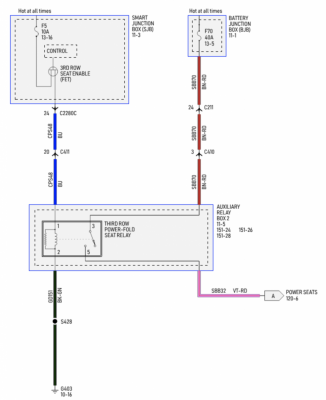
The lift gate had a single plug that was not correct, and the lift gate wouldn't operate entirely. To keep progressing, I then started looking at wiring diagrams to see if we could ensure wiring actually even made it back to the seats.

Going even simpler, I then found the specific wires that go to the third row seat from the breaker box, and after a few iterations, just the actual wires that go to the third row power seat now added specifically to the connectors on the passenger side starting at the pillar back to, and now in, the relay box along with the relays. The seats still don't work, the relays don't seem to fire. Next, later this week, I'll probably have to start using a power meter to see where voltage is missing.

It feels like I'm close.
 
OP
OP
k-bl

k-bl

Active Member
Joined
Oct 29, 2020
Posts
39
Reaction score
32
Location
Indiana
Documenting "where I'm at", to help future third seat enthusiasts...

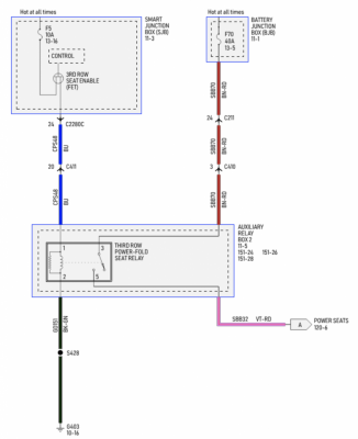
Wiring diagram starting at the "RH C-pillar":
Screen Shot 2020-11-16 at 7.16.17 AM.png

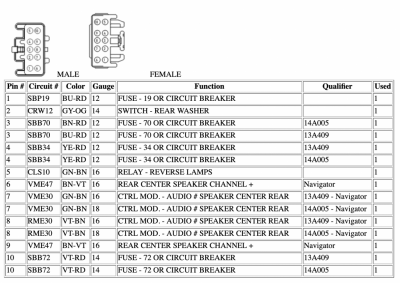
Here is the pinout for the power side's C410 plug. This is where the seats get their power apparently. Pin 3 is of special importance:
Screen Shot 2020-11-16 at 7.13.18 AM.png


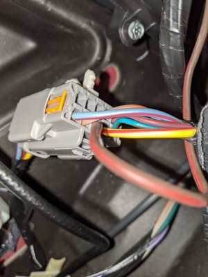
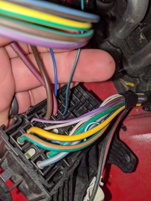
Pin 3 was empty on the male side, but has a cable on the female side. I believe this means that the connection from under the hood, fuse number 70, connects here. So, starting from the power cables you can see the new brown and red addition (C410, located at RH C-pillar, 3 SBB70 BN-RD 12 FUSE - 70 OR CIRCUIT BREAKER 14A005 1) which I swapped from donor wiring harness:
PXL_20201116_115800334.jpg

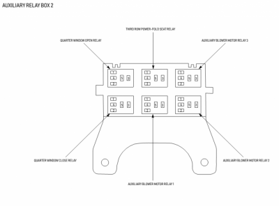
The next we'll follow the brown and red wire to the "Auxiliary Relay Box 2":
Screen Shot 2020-11-16 at 7.22.16 AM.png

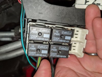
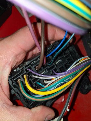
In my vehicle, the "Quarter Window Close Relay", "Quarter Window Open Relay", and "Auxiliary Blower Motor Relay 1" were populated. All other relays were empty. So I as well transplanted the "Third Row Power-Fold Seat Relay" into the "Auxiliary Relay Box 2". Here is a view from the top (this is in the interior loading area near the passenger side tail light), with it still open:
PXL_20201116_115555777.jpg

Continuing because I've reached limit of uploads in next forum post.
 
Last edited:
OP
OP
k-bl

k-bl

Active Member
Joined
Oct 29, 2020
Posts
39
Reaction score
32
Location
Indiana
And of course, the newly added brown and red in from the donor wiring harness (pink out goes to the switches):
PXL_20201116_115607713.jpg

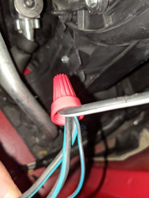
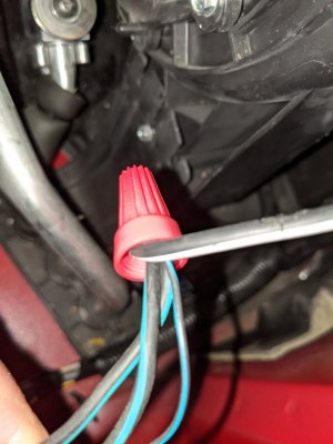
Then the ground side of things (wire nut, don't judge me, I'll solder it later) on the other side of switches:
PXL_20201116_115627328.jpg

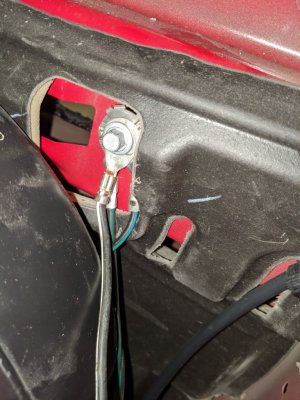
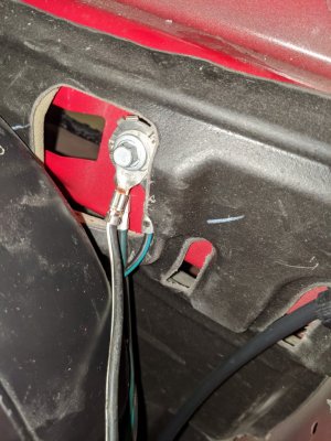
And of course, to the frame:
PXL_20201116_115633546.jpg

So that covers the power side. Next (with repeat picture of the "Auxiliary Relay Box 2" for logical flow) I'll cover the control side.

Continuing because I've reached limit of uploads in next forum post.
 
Last edited:
OP
OP
k-bl

k-bl

Active Member
Joined
Oct 29, 2020
Posts
39
Reaction score
32
Location
Indiana
Starting again at the "RH C-pillar" (repeat picture from https://www.expeditionforum.com/threads/2014-ford-expedition-xl-adding-third-row.45623/#post-416496):
Screen Shot 2020-11-16 at 7.16.17 AM.png

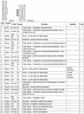
We have the pinout of the C411 plug. This is where the seats get the control apparently. Pin 20 is of special importance:
Screen Shot 2020-11-16 at 7.37.31 AM.png

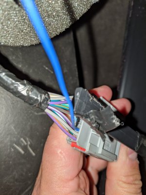
Pin 20 was empty on the male side, but has a cable on the female side. I believe this means that the connection from the passenger side fuse box connects here. So, starting from the control cables you can see the new blue addition (20 CPS48 BU 20 CTRL MOD. - RELAY(S) 3RD ROW SEAT 1) which I swapped from donor wiring harness:
PXL_20201116_115740184.jpg

This connects as well to the "Auxiliary Relay Box 2" (almost repeat image from https://www.expeditionforum.com/threads/2014-ford-expedition-xl-adding-third-row.45623/#post-416497 for continuity):
PXL_20201116_115617947.jpg

The green and black goes to ground (again with the wiring nut from https://www.expeditionforum.com/threads/2014-ford-expedition-xl-adding-third-row.45623/#post-416497 for continuity):
PXL_20201116_115627328.jpg

Continuing because I've reached limit of uploads in next forum post.
 
Last edited:

Trainmaster

Old School Member
Joined
Jun 17, 2017
Posts
3,409
Reaction score
1,928
Location
Rockaway Beach, NY
Looks like you have the wiring diagrams you need.

I've done lots of upgrading to XLs and XLT's but never worked with the seats.

Ford appears to have no less than two sets of wire harnesses; one for XLT trim and one for premium trim. Remember that if a plug or jack doesn't have a wire going to it in an application, the contact inside it is missing too. So don't expect to plug something in and it works. You can add the pins from a donor plug. Same with the fuse box. Some empty locations have no metal contacts in them. Some do.

You have to spend lots of time with those diagrams and pin layouts and a test light to figure this all out. If it were me, I would probably only have run a new hot lead to the seats, if that did the job and not swap the entire harness. But either way would work; decoding the harness and its plugs is just a bit of work A good dependable test light is your friend.
 
Last edited:
OP
OP
k-bl

k-bl

Active Member
Joined
Oct 29, 2020
Posts
39
Reaction score
32
Location
Indiana
Looks like you have the wiring diagrams you need.

I've done lots of upgrading to XLs and XLT's but never worked with the seats.

Ford appears to have no less than two sets of wire harnesses; one for XLT trim and one for premium trim. Remember that if a plug or jack doesn't have a wire going to it in an application, the contact inside it is missing too. So don't expect to plug something in and it works. You can add the pins from a donor plug. Same with the fuse box. Some empty locations have no metal contacts in them. Some do.

You have to spend lots of time with those diagrams and pin layouts and a test light to figure this all out. If it were me, I would probably only have run a new hot lead to the seats, if that did the job and not swap the entire harness. But either way would work; decoding the harness and its plugs is just a bit of work A good dependable test light is your friend.

TY for your reply! I took the plugs apart on the donor wiring harness, and used a paper clip to bring the wire and contact/pin out and inserted it into the existing harness. So that part should be sound. I'll start with a voltage meter next, testing wire by wire back to the back. I also need to test the motors on the seats as well. A small thing, but I think listing it here as something that needs done will help future novice installers.
 
OP
OP
k-bl

k-bl

Active Member
Joined
Oct 29, 2020
Posts
39
Reaction score
32
Location
Indiana
I found a debugging guide and went through each step. I was able to test voltage all the way back to the power cable, and I'm getting over 12 volts to the ground. I then tested the control wire from the passenger side fuse box, and I have essentially no resistance. Fuses are all where they should be, it looks like it may be part of the circuit board simply isn't there to tell the rear seats to be able to work when a door is open and the car is in park.
 
Last edited:

Latest posts

Forum statistics

Threads
53,725
Posts
503,277
Members
47,383
Latest member
imjuststeven
Top