Auxiliary Power plug

Disclaimer: Links on this page pointing to Amazon, eBay and other sites may include affiliate code. If you click them and make a purchase, we may earn a small commission.

Yosemite Sam

Active Member
Joined
Nov 7, 2020
Posts
36
Reaction score
14
Location
Kansas
I have a 2017 Expedition EL. I wanted to use the right, rear auxiliary power plug (cigarette plug) to keep a floating charge across the battery. After connecting the float charger (13.2 VDC) to the plug I was only seeing a 12.5 VDC reading at the battery post.
My question is: why am I seeing a .7 VDC drop from the rear auxiliary power plug to the vehicle's battery post? It's almost as if it's going through a silicon diode before reaching the battery post but that doesn't make any sense because it shows a normal output voltage when measured at the plug!
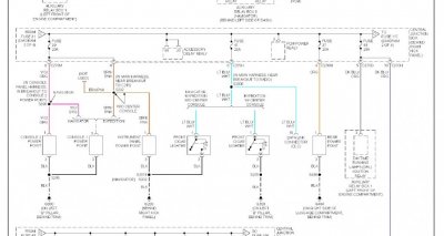
Does anybody have a wiring diagram of the auxiliary plugs that would show the full physical route of the auxiliary plug?
 

ChrisRCNY

Well-Known Member
Joined
Sep 12, 2017
Posts
52
Reaction score
8
Location
Auburn, ny
Depending on how long and what gauge the wires are, it might show that much while charging. It shouldn't be that much with a 1-2amp float charger, though.

Large battery banks get chargers that have separate voltage sense lines to allow the charger to compensate for losses.
 
OP
OP
Yosemite Sam

Yosemite Sam

Active Member
Joined
Nov 7, 2020
Posts
36
Reaction score
14
Location
Kansas
I'm using a lab quality, 50amp, low ripple power supply set at exactly 13.200 VDC. After being connected to the auxiliary power plug
for over 24 hours and indicating 0.121 amps current draw, the battery is showing 12.5 VDC.
As far as the wire gauge goes, according to the fuse that is on that line, it is rated for 20 amps which is moot at this point
since the indicated current draw is only 0.121 amps.
SOMETHING has got to be inline with the wire that feeds the auxiliary power plug and according to my feeble mind it must be a
semi-conductor which would account for the .7 VDC voltage drop.
I'm thinking the only viable way to determine what is going on with this is locate a wiring diagram of the circuit and I really hate to
spend the $$$'s for a shop manual...
 

Yupster Dog

Super Moderator
Staff member
Super Moderator
Joined
Dec 7, 2018
Posts
1,335
Reaction score
870
Location
Virginia
I really hate to
spend the $$$'s for a shop manual...

You can learn how DC power works for free online. Or buy the manual, either way it is not going to work the way you are trying. You need to run way bigger gauge wires than are on that outlet to even attempt charging from that far away.
your alternator is right by your battery and look at the gauge of that wire. and you trying to do it from 4 to 5 times the distance with 12 -14 gauge.

There are supplemental power upgrades you can do. In fact there are threads on here about it.
Maybe if you tell the reason you are trying this someone could help you achieve your goal.
 
OP
OP
Yosemite Sam

Yosemite Sam

Active Member
Joined
Nov 7, 2020
Posts
36
Reaction score
14
Location
Kansas
The reason I want to do it this way is it SHOULD be simple if the auxiliary plug wire ran directly to the fuse block and thence to the battery! Apparently this is not the case but I'd like to know why; because "enquiring" minds want to know!

As far as the wire gauge goes and your expert opinion on DC power; I think I'll pass on your advice. I realize that over 50 years of education in the electronics field doesn't qualify me as an expert so I'll reserve my opinion regarding your advice on DC power education. But thanks anyway.

Just for your edification; I'm not trying to START the vehicle from the auxiliary power port, I only want to float a low current charge on it. Over TIME (rate) I could charge a car battery using very small gauge wire over long distances. The key is the RATE at which one wishes to do the charge. The reason the wire is large, running from the alternator to the battery is because it does TWO things: It has to re-charge the battery after a very high current discharge (starting the vehicle) and two, it must also supply a fairly high current to all the items in the vehicle at the same time, in which case the wire that supports those activities must be of a fairly large gauge (small gauge NUMBER).

Now, as far as your reply goes; it neither answered my questions nor contributed to an intelligent suggestion as to where I might ascertain same. I'm not quite sure why you started up being so confrontational but quite frankly I don't care. You are not my mother and I don't find it necessary to explain to you why I want to do this (or anything). I simply asked if anybody knew how that circuit was designed to function OR if anybody knew where I might locate a wiring diagram of said circuit. You provided neither.
 
Last edited:

07navi

Full Access Members
Joined
Feb 3, 2020
Posts
2,538
Reaction score
593
Location
Mt.Shasta California
The reason I want to do it this way is it SHOULD be simple if the auxiliary plug wire ran directly to the fuse block and thence to the battery! Apparently this is not the case but I'd like to know why; because "enquiring" minds want to know!

As far as the wire gauge goes and your expert opinion on DC power; I think I'll pass on your advice. I realize that over 50 years of education in the electronics field doesn't qualify me as an expert so I'll reserve my opinion regarding your advice on DC power education. But thanks anyway.

Just for your edification; I'm not trying to START the vehicle from the auxiliary power port, I only want to float a low current charge on it. Over TIME (rate) I could charge a car battery using very small gauge wire over long distances. The key is the RATE at which one wishes to do the charge. The reason the wire is large, running from the alternator to the battery is because it does TWO things: It has to re-charge the battery after a very high current discharge (starting the vehicle) and two, it must also supply a fairly high current to all the items in the vehicle at the same time, in which case the wire that supports those activities must be of a fairly large gauge (small gauge NUMBER).

Now, as far as your reply goes; it neither answered my questions nor contributed to an intelligent suggestion as to where I might ascertain same. I'm not quite sure why you started up being so confrontational but quite frankly I don't care. You are not my mother and I don't find it necessary to explain to you why I want to do this (or anything). I simply asked if anybody knew how that circuit was designed to function OR if anybody knew where I might locate a wiring diagram of said circuit. You provided neither.
Yuppie just wanted to zero in on exactly what you were doing to better help you and he did direct you to other threads to further assist you.
 
Last edited:

Yupster Dog

Super Moderator
Staff member
Super Moderator
Joined
Dec 7, 2018
Posts
1,335
Reaction score
870
Location
Virginia
Now, as far as your reply goes; .

I am sorry you thought I was acting like your mother
Your mother did a excellent job. And I am sure she is proud of you. So no need for me to but in

It is super easy to run wiring (Especially the bigger gauge wires not the low gauge big ones) to the front of the vehicle. Probably not as fun as belittling people who are dumb (in your mind) but it will get the job done.

Now that I have ascertained where you are coming from, good luck with getting what you need and on your endeavor.

Had to look up a smart word to end with so you will think I am smart, and maybe you mother can be pruod of me too.
 

Yupster Dog

Super Moderator
Staff member
Super Moderator
Joined
Dec 7, 2018
Posts
1,335
Reaction score
870
Location
Virginia
Yuppie just wanted to zero in on exactly what you were doing to better help you and he did direct you to other threads to further assist you.
I am touched that you would take up for me. Your like the big brother I never wanted.

Don't think this changes anything I will still be nipping at your hack comments tomorrow.
 

Plati

Well-Known Member
Joined
May 4, 2016
Posts
2,782
Reaction score
1,364
Location
.
I cut a section from my 2003 wiring diagram (below) ... looks like power goes only through fuse to the the aux power point shown in this section (cigar lighter). Of course each physical connection will have an associated voltage drop as will each inch of conductor. That voltage drop in the conductor (wires) is a function of current - wire size - distance. There will be some voltage drop at each end of battery power connection to fuse, each end of fuse, each terminal, every connection along the way to final destination. Every place a wire is crimped to a terminal. But Yosemite Sam knew that so that comment is for anyone else who happens to read this.

I also was an Electrical Engineer designing ac & dc power distribution systems for minicomputers (at one point). I have no idea whats going on here mainly because I don't think I have enough information.


power.jpg

I know when I put my trickle charger on my Expy (directly to battery terminals) ... it doesn't instantly go to final battery voltage ... it creeps up slowly. But thats a battery charger. Not sure whats going on with that lab power supply in the OP experiment. My trickle charger does 0.7 amp.
 
Last edited:
OP
OP
Yosemite Sam

Yosemite Sam

Active Member
Joined
Nov 7, 2020
Posts
36
Reaction score
14
Location
Kansas
MrSticker..
Thank you very kindly for your reply. That's exactly what I wanted. Considering from whom I purchased this vehicle, it wouldn't surprise me to learn that there was some modification done to this leg of the 12 volt buss. There was originally an awesome electronics package installed in this vehicle.
Thanks again for the diagram. It's much appreciated.
 

Latest posts

Members online

Forum statistics

Threads
53,696
Posts
503,110
Members
47,344
Latest member
jmdunham2
Top