
Hello,
Thank you for reading and helping me resolve this.
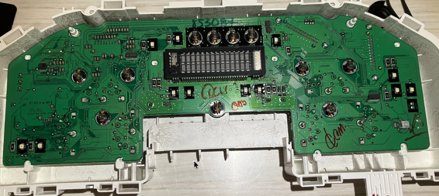
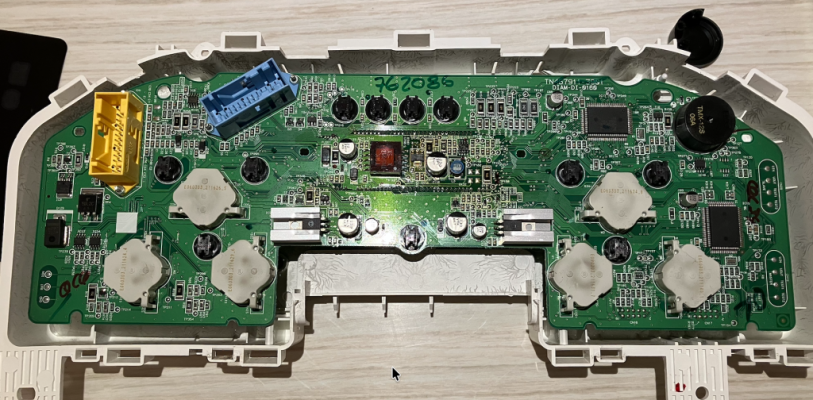
My odometer has stopped working. Sometimes if I hit the dash it will flash on momentarily. It is my understanding that this is due to cracked soldering on the circuit board.
I have delayed repairing this because it didn't really affect vehicle operation. However, I recently replaced a failed A/C compressor and dryer. The compressor itself didn't fail with metal debris, but a seal failed and all the freon leaked out. There was no glitter in the residual PAG oil which looked quite clean.
The A/C worked great for a few hours, then, the compressor would not kick on when i started the vehicle. It would start if I turned the vehicle on and off again. Then, it quit working entirely. Clutch is not engaging on the compressor.
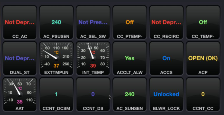
Here are the forscan readings with the A/C on and the vehicle running, but no clutch engagement.
Not sure if it is true, but AI says the following. I figure I need to fix the odometer anyway, so I will attempt to solder the circuit board and make the repair:
"The live FORScan data confirms the instrument cluster communication error is preventing your A/C from working.
The critical data point is the AC_PSUSEN (A/C Pressure Sensor / Sunload Sensor Vref) and AC_SUNSEN (Sunload Sensor) PIDs, which both read a raw value of 240.
What the Data Means
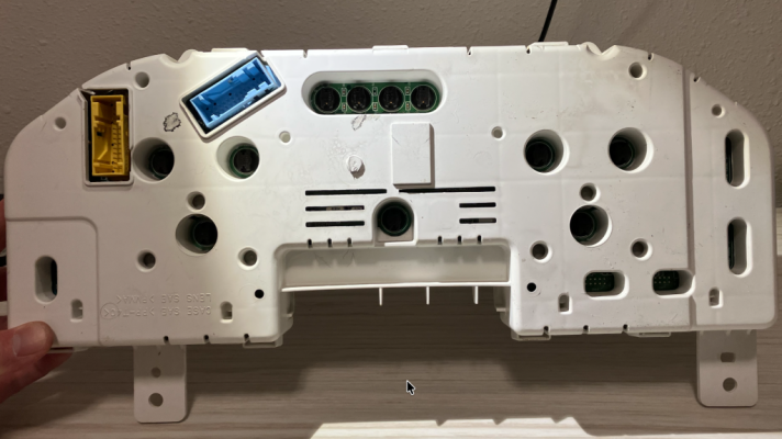
However, I am stuck at this point and cannot access the circuit board. I've gotten the lens off and a few screws beneath the black plastic face. But, tt appears that there are additional screws behind the black plastic face keeping everything together.
How do I get this apart to access the circuit board? I am reluctant to try and force anything at this point.
Thank you for reading and helping me resolve this.
My odometer has stopped working. Sometimes if I hit the dash it will flash on momentarily. It is my understanding that this is due to cracked soldering on the circuit board.
I have delayed repairing this because it didn't really affect vehicle operation. However, I recently replaced a failed A/C compressor and dryer. The compressor itself didn't fail with metal debris, but a seal failed and all the freon leaked out. There was no glitter in the residual PAG oil which looked quite clean.
The A/C worked great for a few hours, then, the compressor would not kick on when i started the vehicle. It would start if I turned the vehicle on and off again. Then, it quit working entirely. Clutch is not engaging on the compressor.
Here are the forscan readings with the A/C on and the vehicle running, but no clutch engagement.
Not sure if it is true, but AI says the following. I figure I need to fix the odometer anyway, so I will attempt to solder the circuit board and make the repair:
"The live FORScan data confirms the instrument cluster communication error is preventing your A/C from working.
The critical data point is the AC_PSUSEN (A/C Pressure Sensor / Sunload Sensor Vref) and AC_SUNSEN (Sunload Sensor) PIDs, which both read a raw value of 240.
What the Data Means
- AC_PSUSEN / AC_SUNSEN at 240: On Ford EATC networks, a raw telemetry value of 240 (or 254/255 depending on the exact firmware string) indicates a data communication dropout or an invalid, uninitialized bus reading.
- ACCS is ON: The EATC module is sending a software request to turn the A/C on, but because the instrument cluster is failing to bridge the network data smoothly to the engine computer, the communication loop is broken.
- ACP is OPEN (OK): The physical A/C pressure switch line is intact, meaning your refrigerant pressure is not what is keeping the system from engaging.
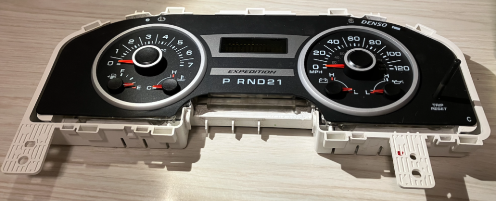
However, I am stuck at this point and cannot access the circuit board. I've gotten the lens off and a few screws beneath the black plastic face. But, tt appears that there are additional screws behind the black plastic face keeping everything together.
How do I get this apart to access the circuit board? I am reluctant to try and force anything at this point.