P0340 97 Exp 5.4 4x

Disclaimer: Links on this page pointing to Amazon, eBay and other sites may include affiliate code. If you click them and make a purchase, we may earn a small commission.

tsgrpr97

Full Access Members
Joined
Jul 1, 2012
Posts
56
Reaction score
2
Location
PA
Yeah. If there's no voltage at the light blue wire, trace it to where it terminates. I don't have fords companion book with wiring diagrams in it, but from looking at the hanes it looks like the light blue feeds off of a grey/red wire from the pcm that also supplies vpwr to other sensors. Try probing the grey/red wire at the intake air temp sensor and checking for voltage there. There should be at least around 11 volts. If there is voltage there, then you've narrowed it down to that blue wire.


Edit:

Sorry it should be 5 volts signal ref from pcm at the iat, not around 11.

It looks like the signal ref is stepped up to the cmp so that explains looking for 10.5 at LT blue. I hate haynes manuals. I want to go check mine for how its wired but dw has it at work.


1 more edit :rolleyes:

The more I'm thinking the less sense everythings making especially without it in front of me.

But if you have less than five volts on lt blue definately trace that one back to where it terminates
 
Last edited:
OP
OP
AuctionExp

AuctionExp

Active Member
Joined
Aug 12, 2012
Posts
38
Reaction score
0
Location
Beaverton, OR
Thanks Toms and tsprgr,

With the key on/engine off I checked the connector for the sensor which is plugged into the air intake tube. I got a reading of 4.65v.

I tried to check for voltage at the back of the connector to the camshaft position sensor, and even up towards where the wires enter the main wiring loom, but I was not able to get a anything above what I found earlier (.010-.013)
 

robbieg

Full Access Members
Joined
Jun 23, 2011
Posts
96
Reaction score
14
Location
FL
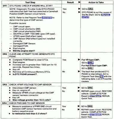
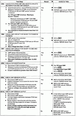
I dont know if any of this will help you but I am going to try and drill down the diagnostic tree based on your responses in this thread. If you need a different branch let me know. I know you already got some of this but I figured Id start at the top.

Preliminary info:
There are two types of camshaft position sensors used, the Variable Reluctance (VR) type, and the Hall Effect type.

The Hall Effect type sensor is used on:
- Mustang 3.8
- Windstar 3.8
- Explorer and Mountaineer 5.0
- E- and F-Series 4.2
- Ranger 4.0
- Explorer 4.0 OHV (VIN X)
All others use the VR type sensor.

-------------------------------------------------
This pinpoint test is intended to diagnose the following:
- Camshaft Position (CMP) Sensor
- Harness Circuits: CMP, VPWR, SIG RTN, PWR GND, CMP/TSS GND
- Powertrain control module
 

Attachments

  • 78117724.gif
    78117724.gif
    8.4 KB · Views: 250
  • 173300086.gif
    173300086.gif
    55.8 KB · Views: 379
  • 78114832.gif
    78114832.gif
    81.9 KB · Views: 342

tsgrpr97

Full Access Members
Joined
Jul 1, 2012
Posts
56
Reaction score
2
Location
PA
I knew there had to be someone on here with the pc/ed manual. :thumbup:
 
OP
OP
AuctionExp

AuctionExp

Active Member
Joined
Aug 12, 2012
Posts
38
Reaction score
0
Location
Beaverton, OR
Thanks Robbie,

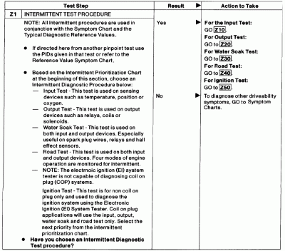
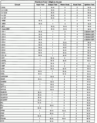
Do you have the step Z1? It's referenced on the second page, but that specific test is not shown on the pages you scanned.

Thanks for checking.
 

robbieg

Full Access Members
Joined
Jun 23, 2011
Posts
96
Reaction score
14
Location
FL
robbieg

Here is Z1, looks like you might need the Ford tool too go much further.
 

Attachments

  • 173125437.gif
    173125437.gif
    46.5 KB · Views: 326
  • 78116390.gif
    78116390.gif
    51.6 KB · Views: 355
  • 78116391.gif
    78116391.gif
    47.4 KB · Views: 320
Last edited:

Latest posts

Forum statistics

Threads
53,644
Posts
502,718
Members
47,256
Latest member
Goff69
Top