Ready Lift 3-2 kit installed with CCD suspension

Disclaimer: Links on this page pointing to Amazon, eBay and other sites may include affiliate code. If you click them and make a purchase, we may earn a small commission.

Dakota4ce

Full Access Members
Joined
May 2, 2018
Posts
119
Reaction score
70
Location
South Dakota
The farther you get from 90°, the quicker more sporadic the reading change is going to be back to the computer. It’s as if you were going from a bumpy road to a washboard road.
All I’m trying to do is get the sensors back to the original engineered factory design operating location and range.
You certainly might get by cheating it, just remember; you can cheat on your wife too, but it’s not recommended and typically has a consequence or two....:D

Yes agree—but you had mentioned it’s designed to be at 90. I was just pointing out it cannot get to 90 at all per the bracket interference.

How much longer do the links end up being after the lift is installed? Anyone know?


Sent from my iPhone using Tapatalk
 

Miekk

Full Access Members
Joined
Jan 9, 2012
Posts
156
Reaction score
32
Location
Madison Lake, MN
Front ones need to be shorter and the rears need to be longer than the factory 4” center-to-center. I know they don’t change the same amount because the sensors aren’t the same distance from the A-arm pivots. Only feedback I’ve ever gotten were estimates. Attached are pictures of front and rear factory setups. Sensor arms are pretty close to 90. AE72C416-5B36-49D3-9D7B-30BDDE4B63CE.jpeg7D071B2C-8065-485D-88D6-C86A7D012655.jpeg
 

Dakota4ce

Full Access Members
Joined
May 2, 2018
Posts
119
Reaction score
70
Location
South Dakota
Got it. So it really doesn’t matter what the specific length is as long as it is somewhat close to
90° at rest.


Sent from my iPhone using Tapatalk
 

michman0969

Member
Joined
Dec 6, 2019
Posts
21
Reaction score
21
Location
Rochester, Michigan
Got it. So it really doesn’t matter what the specific length is as long as it is somewhat close to
90° at rest.


Sent from my iPhone using Tapatalk

My two cents: avoid any potential errors because know one really knows what the true issues could be... I would highly recommend to use his adjustable links and match the arms angle to exactly where they were when you start. Use the angle finder on the measure app on your iphone and set the angle right back and you will have no worry at all! Just did mine a week ago. I apologize if my opinion is unwarranted.


Sent from my iPhone using Tapatalk1453debe27b9388fca805b4a76df134d.jpg31082914d5347e86ffd6267431d9aded.jpg
 
Last edited:

michman0969

Member
Joined
Dec 6, 2019
Posts
21
Reaction score
21
Location
Rochester, Michigan
Front ones need to be shorter and the rears need to be longer than the factory 4” center-to-center. I know they don’t change the same amount because the sensors aren’t the same distance from the A-arm pivots. Only feedback I’ve ever gotten were estimates. Attached are pictures of front and rear factory setups. Sensor arms are pretty close to 90. View attachment 34099View attachment 34100

Miekk, you were a real gentleman when I talked to you on the phone from Michigan and everything you said was right on during our convo. I found that I did not have to switch the left to the right on the struts though I considered it. After a close study of the differences of doing it vs not. I just had a tiny reroute of the solenoid wire from the strut and honestly that was no problem at all. Few zip ties and done. Thank you for making em! Dave D


Sent from my iPhone using Tapatalk
 

Dakota4ce

Full Access Members
Joined
May 2, 2018
Posts
119
Reaction score
70
Location
South Dakota
Ordered a set. You should have seen the ebay auction this evening....I am just over in Sioux Falls.

Hey, thanks to everyone who’s using these. My 17 and 15 yr olds thank you also. It helps support their snowmobiling and motorcycling addictions. :)
 

Dakota4ce

Full Access Members
Joined
May 2, 2018
Posts
119
Reaction score
70
Location
South Dakota
Too all those who have done this and have added the adjustable links, do you happen to know the length you ended up with on the new links? I have the lift installed already.

If the measurement isn't able to be gotten, may just make them so that the sensor arm is around 90 degrees and call it good.

Thoughts welcomed!
 

Tyler Makeig

New Member
Joined
Nov 23, 2019
Posts
3
Reaction score
0
Location
92382
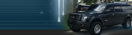
Picked up the wife's new Stealth Expedition Limited today and installed a 3-2 lift on it pretty much immediately. Yes, I know that this isn't supposed to work. Yes I know ReadyLift says it won't work, but it works. Here's what we did:

Before starting we measured each wheel well and recorded it. I don't have the numbers in front of me, but in the end the lift was NOT 3 in the front or 2 in the back.

Next, we used the iPhone measure app to take an angle measurement on each CCD sensor. We then recorded what we had in order to replicate the factory angles with new adjustable arms from this source:


CCD Brackets: 507-381-4260

Once we had our measurements, we put the truck on lift, pulled the wheels off and got to work.

On the front, we found that the electronic solenoid on the shock was clocked differently once the spacers were attached. I believe we could have fixed this by swapping the left and right shocks, but by the time this occurred to us we had the front buttoned up and were not inclined to undo everything and start from scratch. We did have to fashion a tool from right angle bar stock to attach to the lower ball joint after it was removed from the lower control arm. With a block of wood to take up the gap, we used this as a secure way to leverage the lower control arm down so that the strut assembly could be installed. In the end, the CCD wiring had to be slightly re-routed due to the solenoids being 180 degrees out of their original location, but there appear to be no clearance issues. Still, if you plan on doing this, just plan on switching the left and right shocks out for each other once the spacers are installed.

On the rear, we found that the two spacers each needed one of the lower mounting holes modified because the welds were too long and prevented the nuts from tightening flush to the flange. Easy fix, but be prepared for it. We chose to disconnect the CCD arms, then remove the inside lower control arm bolt as well as the lower shock bolt. This allowed the assembly to drop down enough for the shock / spring assembly to be removed easily. The top 3 nuts holding the shock to the frame mount were NOT as easy as the front ones were. In particular the inside two (especially passenger side due to the fuel lines) were a huge pain in the ass. The installation was straight forward, however, but since the CCD is not supposed to be lifted, no mention was made of the CCD solenoid. While re-installing the first one, we discovered the problem with the solenoid clocked 180 degrees out, so we swapped sides and sure enough everything went back together easily. We just tightened the bolts, settled the suspension, and torqued to spec.

Once the truck was back on the ground we installed the adjustable arms and adjusted them until each sensor was at the same angle as stock. Both front arms required approximately 3/4" of thread to be removed in order to achieve the desired angle, whereas the rear arms required nothing more than adjustment. I found that each complete revolution equaled roughly 1 degree, maybe that will help someone from having to take it on and off as many times as I did.

A quick test drive to check the install and no problems or faults were noted. No warnings from the message center, and the ride was exactly as it had been before. Fantastic.

Tomorrow the wheels and tires will be switched, and I'll see if the offset I got will allow me to push the envelope with 34" tires. If not, we have 33s standing by.....

In the end, this kit DID NOT give me the lift I was hoping for. Up front I netted just over 2" and out back I gained about 1.75" This left me still with a noticeable rake to the front, but I'm hopeful that it will settle some with use and at least be level.

FYI the front spacers (22-6615) that they claim to be the "3" in the 3-2 lift are labeled 2.25" level lift for F150. Yes I confirmed with Ready Lift that this was in fact the correct part for this kit.

All in all this was not difficult so if you are holding off because you have the CCD suspension, DON'T.

Pics tomorrow with the tires. It's late and I need another beer.


Ed
I was intending to update what i went through when installing my lift on the CCD given the advice published here I just hadnt got to it yet. Now I have an issue and am hoping to get some advice from others who have a lift installed on CCD and or caution those who are thinking about it.
As for the front, I attempted to switch the lh and rh struts but no matter which way i rotated it i could not get the upper mount to line up aswell as the lower mounting points. i spent a good hour just trying different orientations thinking I was doing something wrong and I decided to move forward without switching the shocks. when the car was on a hoist there did not seem to be any clearance issues.
As for the rear switching the shocks did work as described and caused no issue.
So, lift was done, all was well and good, no driving issues. I was stoked on it!
My wife took the car to the dealer for our free oil change. and they informed her that the cv boots were torn...
as soon as she got back i crawled under there and sure enough.. those solenoids were rubbing on the cv boots and tore both front boots.
I have to find a solution to this issue, I am too deep in this one to go back to stock..
anyway, if anyone has experience with this I would appreciate input. and if you think all is well with your CCD lift.... I suggest you take a look at the cv boots where the axle goes through the knuckle.
 
Top