2000 Expy - Advice on Wiring Lights

Disclaimer: Links on this page pointing to Amazon, eBay and other sites may include affiliate code. If you click them and make a purchase, we may earn a small commission.

soldatlamour

Active Member
Joined
Oct 9, 2011
Posts
33
Reaction score
0
Location
Houston
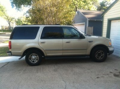
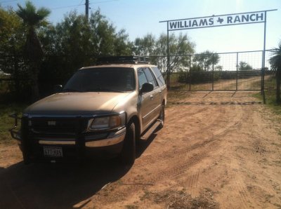
After reading through this forum I am just now making adjustments to my '00 4x2 Expy. I want to add some lights to the basket I just put up, but I want to wire them in such a way that if I wanted/needed to I can pull off the basket and wires without much difficulty.

I'm planning on running the wires in a loom down under the lift gate and (somehow?) into a compartment in the rear of the vehicle. I'm envisioning using an interlocking connector somewhere inside the lift gate. Thus, I can unbolt the basket from the roof, unplug the wires at the connector and, viola, be light free.

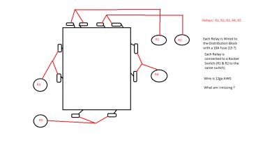
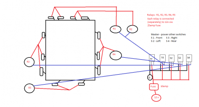
I've done research on wire gauges, relays, switches, etc. I'm fairly comfortable with the basics of getting power to the lights in a safe manner (relays/fuses). My concern: Should I run a heavy gauge wire (2ga?) from the battery back to the rear compartment to tie into a Distribution Panel?

Where I'm stuck is, which is safer: Do I run the load wires further (put the distribution/relay panels in the engine compartment and run the loads to back to the lift gate and up to the lights -- effectively twice the length of the vehicle), -OR- do I run a power supply (heavy gauge wire to the rear compartment where I hope to find a place to put the distribution/relay panels) and, thus, the loads will only run from the rear compartment up to the lights? Which should have the further run?

(I'm sure that if it weren't 1:50 in the morning I could better word my questions!)

If I've overlooked any concern, please let me know. I'm appreciative of any help you can offer.


thanks!
 

Attachments

  • Expedition - the starting point.jpg
    Expedition - the starting point.jpg
    98.4 KB · Views: 58
  • Expedition - transformation begins.jpg
    Expedition - transformation begins.jpg
    98.3 KB · Views: 63

dcarr

Full Access Members
Joined
Aug 23, 2011
Posts
207
Reaction score
9
Location
stafford ct
a big part of the decision would be do you plan on adding anything else to the distribution block in the future. it may be easier to run the smaller wire the longer distance but i would do the larger wire and block to the back for future upgrades and only have to run it once.
 

panda24619

Full Access Members
Joined
May 18, 2010
Posts
5,485
Reaction score
43
Location
San Diego
you want to wire them up to the basket? then you need two things. 1 you really dont need, but it helps you out. a busbar. http://bluesea.com/category/82/35/productline/186 thats what i got. in my center console. have 2 10gauge cables from my battery to that. and the 2nd one is this. something like this. so you can run the wires up there, but then disconnect them if you want to remove the rack. im thinking about getting a big one of these. just get a weather proof one since its going to be out side.
http://www.naturallighting.com/cart/store.php?crn=609
http://crimpingtoolss.com/2011/05/25/wire-connectors-types/
 

Thermo

technical advisor
Joined
Apr 18, 2011
Posts
1,404
Reaction score
65
soldatlamour, as for the wiring aspect of this question, I would ask what else you plan on running electrically in the back of the truck. if the lights are the only thing, then it is a toss up as to which way you go. If you are looking at additional amps, power inverter, etc, then the power block idea will be the far better way to go.

As for wiring up the lights, what wattage lights are you looking at? The reason why I ask this is that most plugs that you are going to find are only rated to handle up to 10 amps per pin. So, this pretty much means you can only run two 55W bulbs off of a single pin. So, if you want to keep all wires off of the top of the truck, then you can only run up to four 55W bulbs (halogen). If you are looking at running HID bulbs or other things like that, then a lot more info is going to be needed to figure out what you are going to need. Let me know. I do wiring for a living and I am sure you are aware of how I plan things out. If not, just ask the guys around here. I'm sure they will have all sorts of things to tell you.
 
OP
OP
S

soldatlamour

Active Member
Joined
Oct 9, 2011
Posts
33
Reaction score
0
Location
Houston
Off Road Lights --- Roof Rack

Thermo,

Thanks for your offer of advice. I don't know what an inverter is ( do I need one ? haha ). I am just planning on lights -- 55w variety. I'm thinking 4 on the front, 2 each on the sides and rear, so 10 @ 55w

What I've learned (hopefully rightly) is that I need to run 12ga wire or larger.

I plan on:
Feeding a Distribution Block with a 2ga wire from the battery (should it be from the solenoid?)

The block will have the fuses and loads to the relays and then to the lights:
1 relay for each two lights -- 5 relays total
What size fuse is appropriate --- 10amps ? 110w/12v = 9.1 -->10 ?
(the front bar with 4 lights will have one switch feeding two relays)

From the relays I will run 4 switches (one for each section of lighting) to
the dash

Am I heading in the right direction? I'm going to try to draw a schematic of what I'm planning on. Please let me know where I'm failing.

Again, thanks for all your help.
 
OP
OP
S

soldatlamour

Active Member
Joined
Oct 9, 2011
Posts
33
Reaction score
0
Location
Houston
My best attempt at a wiring diagram

Pardon the crudeness, but I hope the attach captures what I'm trying to accomplish.

Please let me know if you have any suggestions on improvements. My focus is on safety -- I'll work on the aesthetics later !

thank you
 

Attachments

  • Expedition - Roof Rack Lighting - Wiring Diagram.png
    Expedition - Roof Rack Lighting - Wiring Diagram.png
    25.7 KB · Views: 113

Thermo

technical advisor
Joined
Apr 18, 2011
Posts
1,404
Reaction score
65
soldatlaour, if you are running a fuse block, I would recommend running a 6 gauge wire from the front to the back to give yourself some room for future modifications. I would then also put a 60 amp fuse up front (in the engine bay) to protect the truck from any wiring problems. Then I would run a 15 amp fuse for each 2 lights or a 25 amp fuse for the 4 lights. You want a little bit of room between what the lights are going to be pulling and what the fuse is rated for. Otherwise you will find that the fuses will blow quite often (keep in mind that the lights pull a little bit more current when they initially start up).

As for wiring, I would say to run 18 gauge wiring between the relays and the lights. Any connections outside of the truck should either be inside of the light housings or wrapped up with "raychem" (nuclear grade shrink wrap). You follow this guidance and you will have a lighting system that will outlast your truck.
 

LameSuburbanDad

Full Access Members
Joined
Aug 19, 2010
Posts
204
Reaction score
2
Location
rockwood, MI
since the technical seems well covered, I want to address the practical.

the wires coming out the back end after about 6-8 inches, could you use that as your disconnect location? attaching the lights to the basket, and attaching the wiring harness to the stock crossbar system?

then, if each light doesn't have single plug-n-play connectors you could wire some in to make it mount-unmount faster.

as for space, you have no lack of it behind the panels in the back. if you really had to you could even go under the truck and get in the body that way (surely there is a hole under there, I used to wire caps for F-150's so they can't be THAT different, but check first if you go that route.)
 
OP
OP
S

soldatlamour

Active Member
Joined
Oct 9, 2011
Posts
33
Reaction score
0
Location
Houston
Disconnect Location - Suggestions for Mounting the Lights

DJ - thanks for the tip.

What I was planning on doing was running one bundled/loomed set of wires down one side of the rack and behind the Lift Gate. Then, somewhere in the lift gate area I'd put the disconnect. Thus, allowing me to unplug and go more easily.

Panels - On the passenger side is the cubby hole for the Jack - so I just assume that there is a bunch o' space on the driver side.

I've got Tubed (vs. square/rectangular) rack ---- I'm having trouble fabricating a bracket to hold the lights. Any suggestions?
 

Thermo

technical advisor
Joined
Apr 18, 2011
Posts
1,404
Reaction score
65
soldatlamour, I can think of 2 options.

1) while this is more sturdy, it also assumes you have some tools. You would end up welding some tabs on to the round bars. This would allow you to mount your lights to the tabs and have them very solidly mounted. Down side, you need a welder and the knowledge to weld to the metal of your rack (may be aluminum, may be light gauge steel).

2) this is the more "creative" way. You can run to your local hardware store and they sell brackets similar to what you would use to mount conduit to a wall. they are a flat bracket with a hump in the center. But, in this case, it wouldn't rise quite as much as the conduit brackets do. From there you take two of the brackets and put them back to back and place them around the round tubes of your rack. From there you just have to figure out how to mount the lights to those brackets. This is where some welding ability would come in handy as you can weld basic tabs to one of the brackets.

I wish you lived closer as I would have you come over and we could weld up some tabs for you in no time.
 
OP
OP
S

soldatlamour

Active Member
Joined
Oct 9, 2011
Posts
33
Reaction score
0
Location
Houston
Thermo - thanks for the advice

I don't weld, but I found a welder nearby. He's going to weld 12 tabs ( 4, 3, 3, 2) to my basket rack. I bought 20 tabs for a total of $3.40, and he's going to charge me only $60 to weld. I feel happy about it.

Please comment on my suggested plan of attack for wiring (diagram attached). I want to have a Master switch that "turns on" the other switches. My thought is that I'll have to run only one Power and one Ground (from the M switch) - the other switches' powers/grounds will run a few inches to the Master. Then the 4 switches will run to their respective relays.

I can split the load on S1 to two separate relays, right?

I plan on using 12 AWG wire from the lights to the relays. Let me know if that's OK. Also - with 4 lights ( all lights are 55w ) on the front, 3 on the sides and 2 on the back, will 25amp fuse for each of the relays be sufficient? (Since I'm splitting the front into two relays, perhaps the focus should be on the 3 55w side lights per relay ? )

What size wire should I run on the switches? Is a 10amp fuse good for the switches?

I've found a pocket in the back of the vehicle where I will put a Power distribution center. I plan on making a quick connect between the wires on the rack and the wiring from the distribution center (essentially, the 5 "loads" from the relays and a main grounding wire).

Thank you in advance for your help.
 

Attachments

  • Expedition - Roof Rack Lighting - Wiring Diagram.png
    Expedition - Roof Rack Lighting - Wiring Diagram.png
    37.6 KB · Views: 956
OP
OP
S

soldatlamour

Active Member
Joined
Oct 9, 2011
Posts
33
Reaction score
0
Location
Houston
Updated Drawing

Thermo,

I found a fatal flaw in my diagram.

On my Master switch I didn't have a "load" going anywhere. I had all of the other Switches powered via the 12v source to which I wired the Master.

The attached has the fix (correction is shown in the green wire).

Am I almost home ? haha
 

Attachments

  • Expedition - Roof Rack Lighting - Wiring Diagram.png
    Expedition - Roof Rack Lighting - Wiring Diagram.png
    38.1 KB · Views: 1,140

Thermo

technical advisor
Joined
Apr 18, 2011
Posts
1,404
Reaction score
65
As for the wiring, based on what you have wired up, I would say to run 16 gauge wiring for the lights that are paired up and then 14 gauge wiring for the sets of 3 lights. The 14/16 gauge wiring really only needs to be between where you are splitting the power off from (fuse box?) to the main power part of the relay, from the output of the relay to the lights, between the lights, and from the lights to ground. The actuation wiring for the relays only needs to be 22 gauge wiring. The actuation wiring is very low current stuff, so, that can be smaller gauge wiring.

As for fuses, I would say to run 15 amp fuses for the pairs of lights and then a 20 amp fuse for the sets of 3 lights. But then, the 25's will work too. Rule of thumb is to set the fuse rating at about 125% of the maximum steady state load. Since each of the lights will pull about 5 amps when running, this is about as close as you are going to get.

One final helpful hint is to get yourself 5 colors of wiring. You want a fair amount of black wiring for all of your grounds (obvious to the electricians), but then you will want 4 other colors (red, yellow, orange and blue for example) to run between the relays and the lights. Why the different colors? Easy, when you get that bundle outside of the truck, which wire controls what? Having different colors allows you to figure out which wire goes to which set of lights. So, for example, the red wire would go to the lights powered by R1, the orange wire would go to those from R2, yellow to those from R3, and the blue to those from R4. The same convention should be used when running the wires between the switches and the relays to turn the relays on and off. You will be very thankful for this if you have problems as you will be able to just look at a wire and know where it should go and what power is should have on it at any given situation. I can't tell you how many times I have had to correct things for people when they used 200 feet of the same colored wire for all of their stuff. Makes figuring things out lots of fun.
 
OP
OP
S

soldatlamour

Active Member
Joined
Oct 9, 2011
Posts
33
Reaction score
0
Location
Houston
The Simple Ideas are the Brilliant Ideas

Thermo,

Thanks for the great advice on different colored wiring. That is a fantastic idea.

Can you confirm that on my switch panel I can tie-in the four switches to the master switch. That is, have only the Master wired to a 12v source and then when I flip it 'on' it provides power to the four Switches?

thanks
 
Top