Where to tap into HI beam wiring?

Disclaimer: Links on this page pointing to Amazon, eBay and other sites may include affiliate code. If you click them and make a purchase, we may earn a small commission.

Deadman

Full Access Members
Joined
Mar 17, 2019
Posts
2,561
Reaction score
1,684
Location
Wisconsin
Does anyone know what signal wire to tap into to make my light bar power up with the hi beam headlights? I have it powered off the battery, but I'd like the signal wire to be wired into the hi beams so I don't have to manually switch it on every time and dim it.
Anyone?

Thanks.
 

AKentPhoto

Full Access Members
Joined
Jan 23, 2020
Posts
508
Reaction score
309
Location
New Orleans
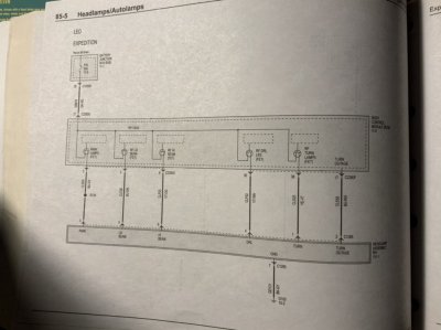
A few of us have been waiting for someone to dig in. I'm afraid it's going to require removing the front bumper. Not sure if halogen setups are different but the LEDs have light control modules which I have accessed from the wheel well but I have yet to find any 12v out for high beams.
 

sjwhiteley

Full Access Members
Joined
Nov 28, 2019
Posts
538
Reaction score
331
Location
Kentucky
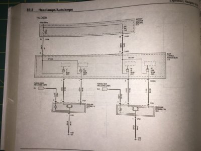
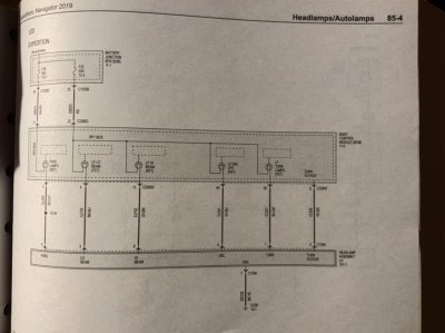
There’s a connector behind the wheel well for each light (remove the fender liner as if you were replacing a bulb on the halogen equipped vehicles). According to the drawing it’s a 4 pin connector: marker, low, high and ground. The drawing says it’s 22gauge with 20gauge for the ground.

the only other option is to go to the BCM with the solid state relays, which looks like a real PITA to access in comparison.

I just ordered some hella spot lights and will be tapping the control wire into the high beam wire going to that connector.

Edit: Looks like GY-BN (Gray/Brown) on the left and VT-OG (Violet/Orange) on the right. Have not confirmed those, yet.
 
Last edited:
OP
OP
D

Deadman

Full Access Members
Joined
Mar 17, 2019
Posts
2,561
Reaction score
1,684
Location
Wisconsin
There’s a connector behind the wheel well for each light (remove the fender liner as if you were replacing a bulb on the halogen equipped vehicles). According to the drawing it’s a 4 pin connector: marker, low, high and ground. The drawing says it’s 22gauge with 20gauge for the ground.

the only other option is to go to the BCM with the solid state relays, which looks like a real PITA to access in comparison.

I just ordered some hella spot lights and will be tapping the control wire into the high beam wire going to that connector.

Edit: Looks like GY-BN (Gray/Brown) on the left and VT-OG (Violet/Orange) on the right. Have not confirmed those, yet.


If you confirm, could you snap a pic please? Thank you!
 

Fozzy

Full Access Members
Joined
Sep 5, 2019
Posts
1,199
Reaction score
1,161
Location
Riverton
AKP! Where have you been? Does the LED look like that behind the fender. If it’s just a plug I will make a custom tap plug so I don’t need to cut or strip any wires. I need my Switch-Pro to have the high beam input.


Sent from my iPhone using Tapatalk
 

AKentPhoto

Full Access Members
Joined
Jan 23, 2020
Posts
508
Reaction score
309
Location
New Orleans
AKP! Where have you been? Does the LED look like that behind the fender. If it’s just a plug I will make a custom tap plug so I don’t need to cut or strip any wires. I need my Switch-Pro to have the high beam input.


Sent from my iPhone using Tapatalk


Sup Foz! Had a baby and work came back at the same time so been busy getting into a normal schedule and routine. Haven't been able to do a thing to the truck, just been enjoying it the best I can.

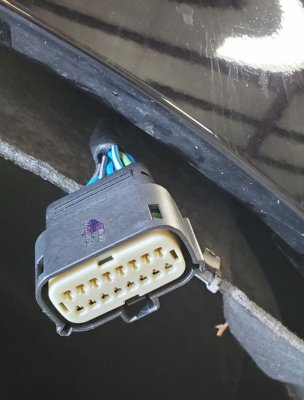
I don't think we have the same light setup. I'm hoping the high and lows will be the same but I will have the drl/arrival lights to deal with. Do you guys have cornering lights? For sharp turns and I think when the blinkers are on? This is the harness I could reach without taking the wheels off... I was in a bit of a hurry and didn't get to take good pics.

20201203_232650.jpg
 

sjwhiteley

Full Access Members
Joined
Nov 28, 2019
Posts
538
Reaction score
331
Location
Kentucky
A06230A6-B80A-4C56-99C0-F0F404F64AFE.jpeg

As an FYI, this is the manual. I’ll be checking the physical wiring this weekend.
 

sjwhiteley

Full Access Members
Joined
Nov 28, 2019
Posts
538
Reaction score
331
Location
Kentucky
Good news/bad news situation on this:

* The connector is on the back of the housing, and you can't get to it from the top (removing the plastic panel along the front of the engine bay) or bottom (through the wheel well) without tiny hands - it's below the turn/drl bulb. The left/drivers side looks like it might be easier, as it doesn't have the washer bottle in the way.

* Good news, you can chase the wire (4 wires wrapped in cloth tape) down, through the wheel where it merges with the turn/DRL wire and connector. It's attached to a couple of tie wrap brackets which you can remove with pliers to get access to the loom.

* Tearing into the cloth tape, you can expose the 4 wires: on the right side of the vehicle, Violet/Orange is the high beam.

* I tested the relay/switch connected to the battery to ensure that the spot lights I added work OK. All is as expected.

* Tapped into the violet/orange wire to test the high beam functionality: it is, indeed, the correct wire. However, the relay buzzes like a hornets nest, and the spot lights have a slight flicker.

* replaced the relay with another one and same situation. This is likely due to the solid state switching supply from the BCM causing the relay to chatter. It needs an 'anti flicker' device going to the relay is my best guess (or a 12V solid state relay, but they don't seem to make a 'plug in' one of those for auto use).

Summary: works, but needs some extra TLC based on what is attached to the high beam wire.

 
OP
OP
D

Deadman

Full Access Members
Joined
Mar 17, 2019
Posts
2,561
Reaction score
1,684
Location
Wisconsin
That might work. A bit pricey, and do not need Bluetooth. I just ordered some capacitors, to see if that will solve the relay chatter.

Also, the relay only chatters while engine is running, not with just the ignition.


Did you ever get this figured out?
 

sjwhiteley

Full Access Members
Joined
Nov 28, 2019
Posts
538
Reaction score
331
Location
Kentucky
Did you ever get this figured out?
Yes, added some capacitors and rectifier diodes. I have two relays in series: one comes on with the fogs and one with the high beams. I added a diode around the relay coil (flyback diode) and a diode in series with the each activation signal from the fog and high beam. I think they are 470uF capacitors. They'll discharge through the relay coil.

Chucked the relays and capacitors in a small plastic box. Not mounted, yet, just thrown in next to the battery.
 
OP
OP
D

Deadman

Full Access Members
Joined
Mar 17, 2019
Posts
2,561
Reaction score
1,684
Location
Wisconsin
Yes, added some capacitors and rectifier diodes. I have two relays in series: one comes on with the fogs and one with the high beams. I added a diode around the relay coil (flyback diode) and a diode in series with the each activation signal from the fog and high beam. I think they are 470uF capacitors. They'll discharge through the relay coil.

Chucked the relays and capacitors in a small plastic box. Not mounted, yet, just thrown in next to the battery.


Nothing is simple anymore. lol I don't even know why those things are, muchless how to do that. lol
 

AKentPhoto

Full Access Members
Joined
Jan 23, 2020
Posts
508
Reaction score
309
Location
New Orleans
* Good news, you can chase the wire (4 wires wrapped in cloth tape) down, through the wheel where it merges with the turn/DRL wire and connector. It's attached to a couple of tie wrap brackets which you can remove with pliers to get access to the loom.

Any pictures of where these wires run? This is huge! Can't thank you enough...

I have that relay and have been using it as a stop gap til I can get the full trigger system in. We are in the middle of moving at the moment, but will definitely give it a whirl when I get a chance.
 

Fozzy

Full Access Members
Joined
Sep 5, 2019
Posts
1,199
Reaction score
1,161
Location
Riverton
Yes, added some capacitors and rectifier diodes. I have two relays in series: one comes on with the fogs and one with the high beams. I added a diode around the relay coil (flyback diode) and a diode in series with the each activation signal from the fog and high beam. I think they are 470uF capacitors. They'll discharge through the relay coil.

Chucked the relays and capacitors in a small plastic box. Not mounted, yet, just thrown in next to the battery.

Please pics and a write up.


Sent from my iPhone using Tapatalk
 

sjwhiteley

Full Access Members
Joined
Nov 28, 2019
Posts
538
Reaction score
331
Location
Kentucky
Nothing is simple anymore. lol I don't even know why those things are, muchless how to do that. lol
Luckily, doing such things is in my skill set, but am sometimes unaware that people don't know that stuff.

I need to rearrange the wires a bit (currently set as a semi-permanent 'proof of concept' so it isn't pretty) and will take some pictures for those that want it, as will as diagrams as appropriate. May be a few weeks.
 
Top