I think the pump seal blew out

Disclaimer: Links on this page pointing to Amazon, eBay and other sites may include affiliate code. If you click them and make a purchase, we may earn a small commission.

OP
OP
B

Bowesmobile

Full Access Members
Joined
Jul 7, 2012
Posts
397
Reaction score
45
Location
Clarkston, Mi
Thats how this one started. Just small drips, then BOOM! Massive leak and I almost didnt make it home. Im sure you can find help to rebuild the 4R100. Honestly I wish I had the cash to do the manual swap. But every ZF5 trans I come across is at least 1 1/2 times the cost of the rebuild. So it doesnt make financial sense to do that.
 
OP
OP
B

Bowesmobile

Full Access Members
Joined
Jul 7, 2012
Posts
397
Reaction score
45
Location
Clarkston, Mi
Uhhh, no.

Tomorrow it will be evicted from the trans well of my expy. So by this weekend things are going to get moving! It will be awesome. I hope.
 
OP
OP
B

Bowesmobile

Full Access Members
Joined
Jul 7, 2012
Posts
397
Reaction score
45
Location
Clarkston, Mi
Its out! There were some other issues I found along the way. The extension between the trans and transfer case only had three of the six bolt holding the transfer case on. Two snapped inside the trans housing and I'll have to drill those out. The torsion bar crossmember does not have to be removed to pull the trans. If you take the transfer case off first, you can swing the tail shaft to the drivers side and slide it down with some persuation. Definitely worth not having to remove the torsion bar cross member. Also, I pulled the shifter arm and left it on the cable. Its easier to not have to re-adjust the shifter.
 

Attachments

  • IMG_20150613_094434190.jpg
    IMG_20150613_094434190.jpg
    90 KB · Views: 42
  • IMG_20150613_094507019.jpg
    IMG_20150613_094507019.jpg
    99.2 KB · Views: 44
  • IMG_20150613_094551949.jpg
    IMG_20150613_094551949.jpg
    96.9 KB · Views: 37
  • IMG_20150613_094600301.jpg
    IMG_20150613_094600301.jpg
    89.4 KB · Views: 39
  • IMG_20150613_131009611.jpg
    IMG_20150613_131009611.jpg
    93.3 KB · Views: 42
OP
OP
B

Bowesmobile

Full Access Members
Joined
Jul 7, 2012
Posts
397
Reaction score
45
Location
Clarkston, Mi
Here are some more pictures of what I found on the extension.
 

Attachments

  • IMG_20150613_131025466.jpg
    IMG_20150613_131025466.jpg
    100.8 KB · Views: 42
  • IMG_20150613_135519871.jpg
    IMG_20150613_135519871.jpg
    99.2 KB · Views: 43
  • IMG_20150613_135552062.jpg
    IMG_20150613_135552062.jpg
    99.5 KB · Views: 41
OP
OP
B

Bowesmobile

Full Access Members
Joined
Jul 7, 2012
Posts
397
Reaction score
45
Location
Clarkston, Mi
It seems the extension bolts are something to keep an eye on. The two that snapped off have loctite on the threads. So this was an issue sometime before this. Anyone with a first gen should regularly inspect the extension to trans housing bolts and tighten them if necessary. It causes a bad vibration and can possibly lead to the transfercase separating from the transmission.
 
OP
OP
B

Bowesmobile

Full Access Members
Joined
Jul 7, 2012
Posts
397
Reaction score
45
Location
Clarkston, Mi
The 4R70W rebuild!

This has been a busy summer! So many things going on and hardly any time for this. Im going to do my best to piece together my rebuild. Its been far too long since I posted and I have A LOT to write. Im going to start off by saying this. When rebuilding a trans keep everything clean. Its paramount to the rebuild. This will stop any problems down the road.

Okay, so here goes!

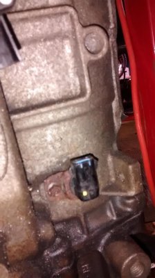
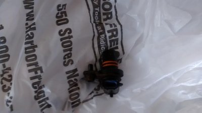
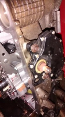
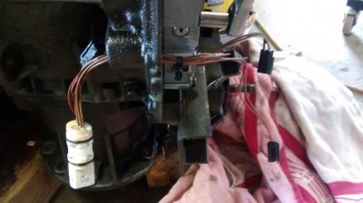
First thing is to remove the shaft speed sensor. It will be damaged at disasembly if you do not remove this first. There is a picture of it removed. I believe its held in with a 8mm bolt.

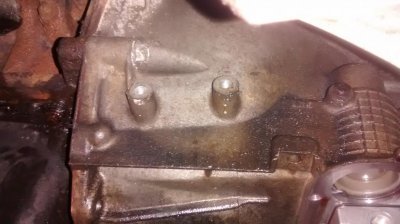
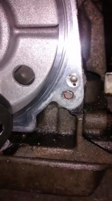
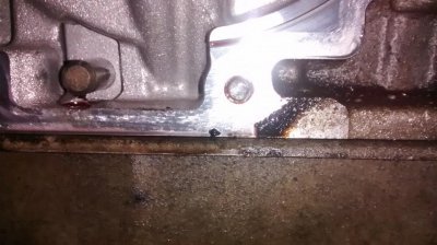
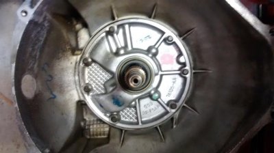
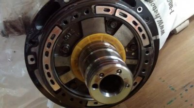
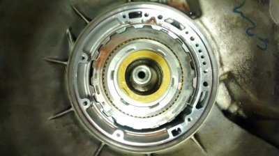
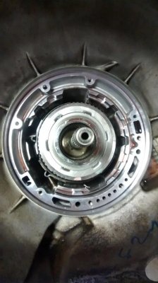
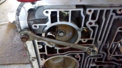
Then, pull the front pump. All the bolt holes are clearance holes. Two have a threaded section thats larger than the through hole so you can thread a larger diameter bolt jn and pull the pump out. On all the rebuilds I read this was not made clear. This threaded section is the right size for one of the transfer case to extension bolts. I used two of those and a ratchet strap. With a quick jerk, the p u mp came free. I used the two bolts I threaded in to lift the pump out.
 

Attachments

  • IMG_20150620_144613643.jpg
    IMG_20150620_144613643.jpg
    90.7 KB · Views: 28
  • IMG_20150620_144730667.jpg
    IMG_20150620_144730667.jpg
    84.2 KB · Views: 32
  • IMG_20150620_144953864.jpg
    IMG_20150620_144953864.jpg
    92.6 KB · Views: 27
Last edited:
OP
OP
B

Bowesmobile

Full Access Members
Joined
Jul 7, 2012
Posts
397
Reaction score
45
Location
Clarkston, Mi
After sliding off the pump, there is the yellow spacer. None of the other rebuolds I read talked about it. This takes up any slack left from stacking shafts and torrington bearings. Its re-measured before you put the pump back on at re-assembly. They have different colors and each color is a set thickness. There is a notch on the spacer that slides into a recess in the pump. That keeps the spacer from rotating.
Next pull the intermediate clutches out. Use a flat head screw driver on the outer edge. Lifting on the metal disc under each fiber clutch plate. They will not come out easily, and you will probably have to wiggle them to slide off the inner splines. Unless you have the trans in a horzontal position. But sadly I dont. The bottom plate is shaped and will only go in one way. The raised portion points toward the back of the trans. Sorry I dont have a picture of that yet.
 

Attachments

  • 2015-06-20 15.03.19.jpg
    2015-06-20 15.03.19.jpg
    92.5 KB · Views: 23
  • 2015-06-20 15.03.02.jpg
    2015-06-20 15.03.02.jpg
    96.7 KB · Views: 27
  • 2015-06-20 15.10.41.jpg
    2015-06-20 15.10.41.jpg
    94.8 KB · Views: 24
OP
OP
B

Bowesmobile

Full Access Members
Joined
Jul 7, 2012
Posts
397
Reaction score
45
Location
Clarkston, Mi
From here you can see where the overdrive servo contacts the overdrive band. At this point we have other things to remove before we can continue tearing down the internals.
The next step is to remove the shift position switch. Then the valve body. There are a lot of bolts to remove the valve body. Keep everything together in little bins or sandwich bags so nothing gets lost. Note the wiring harness. This is different between 1997 and 1998 4R70W's. The 1998 and later have a black hard plastic wiring harness thats nicer than what you see here.
 

Attachments

  • 2015-06-20 15.10.41.jpg
    2015-06-20 15.10.41.jpg
    94.8 KB · Views: 25
  • 2015-06-20 15.12.15.jpg
    2015-06-20 15.12.15.jpg
    92.9 KB · Views: 27
  • 2015-06-20 15.11.50.jpg
    2015-06-20 15.11.50.jpg
    99.5 KB · Views: 27
OP
OP
B

Bowesmobile

Full Access Members
Joined
Jul 7, 2012
Posts
397
Reaction score
45
Location
Clarkston, Mi
Now that the valve body is unbolted, you can see the hydraulicly driven servos. Each one has its function. On the upper left is the overdrive servo. On the bottom left is the reverse/low band servo. On the top right I think the the 2-3 accumulator. The first one to remove is the overdrive servo. One trick I picked up if you dont have the specialty tool is to use a trans pan bolt and combination wrnech as a lever on a socket. This compresses the servo and allows you to remove the snap ring.

On another note. Be patient when disassembling the trans. The wiring harness is held in place under the valve body. DONT USE A HAMMER TO TRY AND SLIDE IT OUT OF THE MOUNTING HOLE! Unless you want to buy a new one.
 

Attachments

  • 2015-06-20 15.33.20.jpg
    2015-06-20 15.33.20.jpg
    97.3 KB · Views: 27
  • 2015-06-20 15.21.05.jpg
    2015-06-20 15.21.05.jpg
    93.4 KB · Views: 26
  • 2015-06-20 15.38.57.jpg
    2015-06-20 15.38.57.jpg
    95.5 KB · Views: 28
Top