Disclaimer: Links on this page pointing to Amazon, eBay and other sites may include affiliate code. If you click them and make a purchase, we may earn a small commission.

stamp11127

Full Access Members
Joined
Mar 10, 2012
Posts
6,218
Reaction score
1,250
Location
Temple, Georgia
I won't have access to wiring diagrams until I go back to work in August. Until then if another member could post the power distrubution diagrams we can get started with tracing the circuits. If no one posts them, you can get them off ebay in dvd form.
 
OP
OP
03NavigatorGuy

03NavigatorGuy

Full Access Members
Joined
May 9, 2014
Posts
106
Reaction score
5
Location
Memphis TN
So I checked the neutral safety switch AKA: Digital Transmission Range Sensor (DTR), and there is no power at the transmission connector.

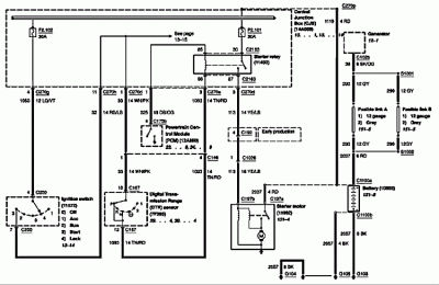
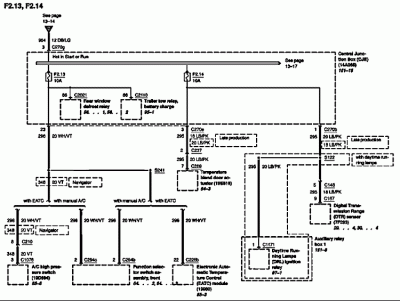
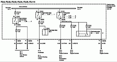
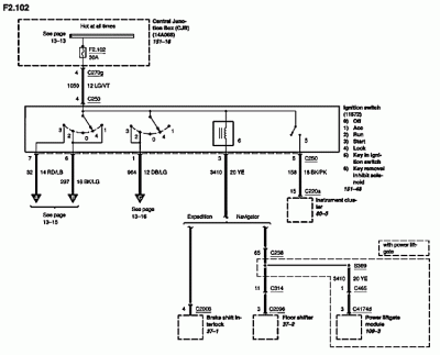
Here are the diagrams that I am getting from ALLDATA, if there are others needed, let me know. This is learn as I go experience for me, so what might be obvious to some here might take me a bit to figure it out.

View attachment 35569

View attachment 35570

View attachment 35571

View attachment 35572

CBJtoPCM:DTR:START.gif

CJBtoNeutralSafteyDTR.gif

CJBtoPCMFuelRelay.gif

CJBtoIGNFlrSftTailGt.gif
 
Last edited:

stamp11127

Full Access Members
Joined
Mar 10, 2012
Posts
6,218
Reaction score
1,250
Location
Temple, Georgia
You really can't read those. Print the diagrams as pdf files and upload those - heck of a lot easier to read.
 

stamp11127

Full Access Members
Joined
Mar 10, 2012
Posts
6,218
Reaction score
1,250
Location
Temple, Georgia
Slightly better. Looking at CBJtoPCM_DTR_STARTPDF.pdf are you able to read and understand the drawing? The answer will determine how detailed I need to make future replies. Also do you understand the difference between series and parallel connections?
 
OP
OP
03NavigatorGuy

03NavigatorGuy

Full Access Members
Joined
May 9, 2014
Posts
106
Reaction score
5
Location
Memphis TN
Yes, I believe I am grasping the what the diagram is showing: fuse # 102 sends power to ignition switch, fuse #101 sends power to starter relay, which will send power to the send power to the Starter motor if it gets the correct signal for the DTR and the PCM. I understand the basic concept of serial and parallel connections. Hopefully I can keep up!
 

stamp11127

Full Access Members
Joined
Mar 10, 2012
Posts
6,218
Reaction score
1,250
Location
Temple, Georgia
In your first post you state when you jump the starter it cranks. Where are you jumping it at?

You can use a meter or test light to follow the path the electricity follows starting at fuse 102. I use sewing needles inserted into connectors as test points instead of poking holes in the wire insulation.

With the negative meter probe or test lights lead wire placed on a good ground, you use the red probe or test light probe to find positive voltage at specific points:

Test fuse 102 on both test points and follow the wire on the diagram

Test the pin 4 light green/violet wire at the ignition switch

Check pin 11 red/ light blue wire back at the central junction box with the ign switch in start

Check pin 3 tan/red wire also at the central junction box trans in park or neutral

Pull starter relay - check 86 when key is in start, trans in park/neutral

You will have power at some points then you will loose it at the next point tested. The problem then lies between the last two points you tested.

If you have power all the way to the pin 3 then the pcm isn't grounding the circuit or you have a failed starter relay. One way to verify is to ground pin 1 dark blue / orange wire that leads to the pcm

What you are checking is the control portion of the starting circuit. It is wired in series - any part fails in the circuit and it doesn't work.
 
OP
OP
03NavigatorGuy

03NavigatorGuy

Full Access Members
Joined
May 9, 2014
Posts
106
Reaction score
5
Location
Memphis TN
Jumping the starter from underneath - old school. Tomorrow if in between the rain, I will try and check those connections you mention and see where it leads. Thank you for your help!
 

stamp11127

Full Access Members
Joined
Mar 10, 2012
Posts
6,218
Reaction score
1,250
Location
Temple, Georgia
OK, so one test before doing the above steps. Pull the starter relay in the central junction box. Using a jumper wire, jump 30 to 87. If the starter works then the issue is on the control side of the starter relay. If it doesn't then it is on the high current side.
 
OP
OP
03NavigatorGuy

03NavigatorGuy

Full Access Members
Joined
May 9, 2014
Posts
106
Reaction score
5
Location
Memphis TN
Had to wait for a break in the rain. But when I jumped 30 to 87 it did cause the starter to crank!
 
Top