P0340 97 Exp 5.4 4x

Disclaimer: Links on this page pointing to Amazon, eBay and other sites may include affiliate code. If you click them and make a purchase, we may earn a small commission.

OP
OP
AuctionExp

AuctionExp

Active Member
Joined
Aug 12, 2012
Posts
38
Reaction score
0
Location
Beaverton, OR
I have not heard about any shops yet. So I decided to do some further testing.

I found a troubleshooting guide online, and one of the steps is to check the VPWR Voltage to the CMP sensor. With the sensor disconnected and the Key On and Engine Off, it has me measure the voltage between the VPWR on the CMP connector and the Negative Battery terminal.

There are two wires coming from my camshaft position sensor. One is Light Blue and the other is Green. Following the steps I get a voltage between .010 and .013 between the Green wire side of the connector and the negative battery terminal. Note: I was not able to get a voltage reading from the Light Blue side of the connector.

According to the steps if the voltage is less than 10.5 volts, then a Repair of the open circuit is the next step.

Does this mean that there is a broken wire somewhere that is not letting the vehicle send power to the Camshaft Position Sensor?

Has anyone else run into a similar issue?
 
Last edited:

Exia

Full Access Members
Joined
Jun 27, 2012
Posts
261
Reaction score
25
Location
Kentucky
If that were the case you would still be throwing a DTC, but did you reset the ecu after installing the sensor? If not unplug your battery for 30 minutes and cycle your key a few times.. It may need to relearn.. otherwise go to your local library and pick up a haynes or chilton manual
 
Last edited:

toms89

technical advisor
Joined
Mar 13, 2011
Posts
5,177
Reaction score
440
Location
MD
I have not heard about any shops yet. So I decided to do some further testing.

I found a troubleshooting guide online, and one of the steps is to check the VPWR Voltage to the CMP sensor. With the sensor disconnected and the Key On and Engine Off, it has me measure the voltage between the VPWR on the CMP connector and the Negative Battery terminal.

There are two wires coming from my camshaft position sensor. One is Light Blue and the other is Green. Following the steps I get a voltage between .010 and .013 between the Green wire side of the connector and the negative battery terminal. Note: I was not able to get a voltage reading from the Light Blue side of the connector.

According to the steps if the voltage is less than 10.5 volts, then a Repair of the open circuit is the next step.

Does this mean that there is a broken wire somewhere that is not letting the vehicle send power to the Camshaft Position Sensor?

Has anyone else run into a similar issue?

If the test was performed properly it does indicate you have an open circuit. This would be a broken wire or bad connection or connector somewhere. The camshaft position sensor on the 2v 5.4's and 4.6's cannot be installed incorrectly and making sure the motor is at top dead center with this particular sensor makes no sense to me?! Maybe these links are referencing the v6 with a different style sensor?

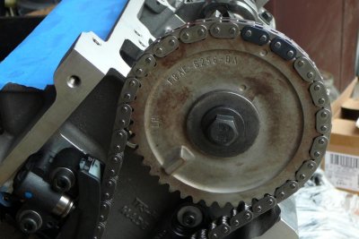
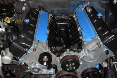
In the one photo you can see the lobe or high spot on the cam gear which the sensor registers. The other just shows the sensor on the right hand side of the timing cover.....assume yours is the same?? I can see no way the cam sensor can possibly be mistimed in this application?! Other applications or sensors will and can obviously differ.
 

Attachments

  • 5.4 built block 004.jpg
    5.4 built block 004.jpg
    94.5 KB · Views: 1,187
  • 7-1-11 007.jpg
    7-1-11 007.jpg
    100.6 KB · Views: 1,204
OP
OP
AuctionExp

AuctionExp

Active Member
Joined
Aug 12, 2012
Posts
38
Reaction score
0
Location
Beaverton, OR
Thanks Toms89,

Yes, my sensor is in the very same place as yours. And it is the 2 wire VR (variable reluctance) type.

Since this is the only sensor/circuit that I am getting a check engine light for, I am thinking that somewhere there is an open/broken wire/bad connector?

I checked and Standard Ignition does make a replacement connector in case the problem is with the connector itself.

I wanted to see how test how far back in the wiring the problem may be, and I was thinking that I could start with the connector and work my way back.

Thoughts?
 

Exia

Full Access Members
Joined
Jun 27, 2012
Posts
261
Reaction score
25
Location
Kentucky
ok class in session

P0340 OBD-II Trouble Code

Technical Description
Camshaft Position Sensor Circuit Malfunction

What does that mean?

This indicates that a problem was detected in the camshaft position sensor circuit. Since it says circuit, that means the problem could lie in any part of the circuit - the sensor itself, the wiring, or the PCM. Don't just replace the CPS (camshaft position sensor) and think that will definitely fix it.

Symptoms

Symptoms can include:
Hard starting or no start
Rough running / misfiring

Causes

A code P0340 could mean one or more of the following has happened:

a wire or connector in the circuit could be grounded/shorted/broken
the camshaft position sensor may have failed
the PCM may have failed
there exists an open circuit

Possible Solutions

With a P0340 OBD-II trouble code, diagnosis can be tricky at times. Here are some things to try:

Visually inspect all the wiring and connectors in the circuit
Check for continuity in the circuit wiring
Check the operation (voltage) of the camshaft position sensor
Replace the camshaft position sensor as required
Check the crankshaft position circuit as well
Replace circuit wiring and/or connectors as required
Diagnose/replace the PCM as required

How does a camshaft position sensor work

A camshaft position sensor,or cylinder identification sensor is used to determin the engine cycle position the information is used to provide individual cylinder ignition and injection cotrol.Many engine management systems use an inductive type of sensor that is located near the camshaft;when the camshaft rotates a single signal is passed to the ECU to indicate a reference point in the engine cycle.Some system manufactures may use a Hall effect-type sensor.

Which can also relate to previous how-tos about "setting" TDC
 

toms89

technical advisor
Joined
Mar 13, 2011
Posts
5,177
Reaction score
440
Location
MD
ok class in session

P0340 OBD-II Trouble Code

Technical Description
Camshaft Position Sensor Circuit Malfunction

What does that mean?

This indicates that a problem was detected in the camshaft position sensor circuit. Since it says circuit, that means the problem could lie in any part of the circuit - the sensor itself, the wiring, or the PCM. Don't just replace the CPS (camshaft position sensor) and think that will definitely fix it.

Symptoms

Symptoms can include:
Hard starting or no start
Rough running / misfiring

Causes

A code P0340 could mean one or more of the following has happened:

a wire or connector in the circuit could be grounded/shorted/broken
the camshaft position sensor may have failed
the PCM may have failed
there exists an open circuit

Possible Solutions

With a P0340 OBD-II trouble code, diagnosis can be tricky at times. Here are some things to try:

Visually inspect all the wiring and connectors in the circuit
Check for continuity in the circuit wiring
Check the operation (voltage) of the camshaft position sensor
Replace the camshaft position sensor as required
Check the crankshaft position circuit as well
Replace circuit wiring and/or connectors as required
Diagnose/replace the PCM as required

How does a camshaft position sensor work

A camshaft position sensor,or cylinder identification sensor is used to determin the engine cycle position the information is used to provide individual cylinder ignition and injection cotrol.Many engine management systems use an inductive type of sensor that is located near the camshaft;when the camshaft rotates a single signal is passed to the ECU to indicate a reference point in the engine cycle.Some system manufactures may use a Hall effect-type sensor.

Which can also relate to previous how-tos about "setting" TDC

Wow...what in this post has anything to do with installing camshaft position sensor only with motor at TDC?? Yes I get that cams sensors indicate cam position in relation to top dead center to properly time fuel and spark but this means nothing as far as installing sensor with motor at top dead center.

edit:

Just checked haynes manual... V6 sensor is mounted to a gear driven synchronize assembly so setting motor to TDC is critical. It appears the V6 is an older pushrod motor and the sensor mounts where the distributor would if they didnt swap over to individual coil packs with ecu control. There is a long drawn out procedure for replacement.

The V8 models removal procedure as per the haynes manual:

Remove retaining screw and seperate the camshaft sensor from cylinder head. Installation is the reverse of removal.

Since the expys do not come with a V6 I think we can disregard worrying about tdc. This confirms what I previously posted.

I do understand engine operation, function, theory as it has been a hobby of mine for the past 30 years. I rebuilt a motor of mine when I was 15 with my fathers help of course. My built expy is only my latest project.
 
Last edited:

Exia

Full Access Members
Joined
Jun 27, 2012
Posts
261
Reaction score
25
Location
Kentucky
really? He just replaced it "Tom" I just gave current issues ON WHY it could still be acting up, as far as the TDC, even my local ford dealer "RECOMMENDED" tdc. sheesh, and that post was ment for Auction, to give him a better understanding of how it works.. Reguardless if you knew.. If people would help break things down instead of being all technical and give full info it helps more

I may not have the years, but my Steeda Stage 2 was built from the frame up, by my brothers and I. I know a little.. I also am not afraid to ask and learn when there is something I dont fully understand.. And on my behalf I should have posted that info first my fault

Sorry bad day
 
Last edited:

tsgrpr97

Full Access Members
Joined
Jul 1, 2012
Posts
56
Reaction score
2
Location
PA
If you're going to copy and paste, copy and paste from a useful source, like the shop manual. Anyone can search e-how.
 

Exia

Full Access Members
Joined
Jun 27, 2012
Posts
261
Reaction score
25
Location
Kentucky
That wasnt ehow, btw.. And if everyone did their own searching than forums would be a thing of the past. *****
 

toms89

technical advisor
Joined
Mar 13, 2011
Posts
5,177
Reaction score
440
Location
MD
If the test was performed properly it does indicate you have an open circuit. This would be a broken wire or bad connection or connector somewhere. The camshaft position sensor on the 2v 5.4's and 4.6's cannot be installed incorrectly and making sure the motor is at top dead center with this particular sensor makes no sense to me?! Maybe these links are referencing the v6 with a different style sensor?

In the one photo you can see the lobe or high spot on the cam gear which the sensor registers. The other just shows the sensor on the right hand side of the timing cover.....assume yours is the same?? I can see no way the cam sensor can possibly be mistimed in this application?! Other applications or sensors will and can obviously differ.

really? He just replaced it "Tom" I just gave current issues ON WHY it could still be acting up, as far as the TDC, even my local ford dealer "RECOMMENDED" tdc. sheesh, and that post was ment for Auction, to give him a better understanding of how it works.. Reguardless if you knew.. If people would help break things down instead of being all technical and give full info it helps more

I may not have the years, but my Steeda Stage 2 was built from the frame up, by my brothers and I. I know a little.. I also am not afraid to ask and learn when there is something I dont fully understand.. And on my behalf I should have posted that info first my fault

Sorry bad day

Not trying to compare knowledge base.... just was a bit offended that you were "taking me to class". lol...

My original post was to intended to help the OP. It is not an easy thing to set these motors to TDC and is not required for this application. I had installed the sensor when I put my motor together and it just raised a red flag when I viewed the post. I viewed your link and realized it was likely a V6 they were referencing and said so.

My apologies to AuctionExpy for getting off topic. Since you tried a new sensor odds are there is a fault in the circuit. The haynes manual says to check for voltage at the connector with ignition on but not running. With the sensor out and on table top you can check for voltage on the ac scale while running metal pass the tip. Also confirm sure the sensor is/was seated well when installed.

Its rare that a wire goes bad unless it is physically damaged, spliced or sharply bent. So if the circuit is found to be bad I would check all connections first.
 
Top