Programming Mirrors

Disclaimer: Links on this page pointing to Amazon, eBay and other sites may include affiliate code. If you click them and make a purchase, we may earn a small commission.

Ghostwolf

Member
Joined
Nov 19, 2019
Posts
24
Reaction score
10
Location
Ann Arbor, MI
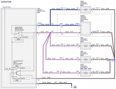
I was going to create a new thread but thought I would update this one instead. I believe there may be a way to do this for 2015-17 vehicles. After studying the wiring diagrams, it may be possible to tap into the driver door lock motor wire (Blue-Green) near connector C465 (pin 36) at the LH "C" pillar. By running a wire from here, through a diode, and connecting to the Grey-Brown wire coming from connector C311 (pin 2) under the driver's seat, it would provide a remote input to the Driver's Door Module (DDM) to fold/unfold the power mirrors.

If I'm reading the diagrams correctly, whenever you use the keypad or the remote to lock the doors, a 12V pulse will appear on the Blue-Green wire at connector C465, pin 36. The same thing will happen if you enter the code on the keypad or use the remote to unlock the doors, but current will be flowing in the opposite direction. Either way, tapping this wire will provide a brief 12V pulse during remote lock and unlock. Connecting this pulse to the power fold input on the DDM (via an isolating diode) should cause the mirrors to fold/unfold automatically during remote lock/unlock.

There is, however, a caveat to this approach: If the mirrors are folded, the next input from the fold switch causes them to unfold. Thus, if you were to fold the mirrors yourself using the switch before you locked the vehicle, they would then unfold as soon as you locked the door with the remote or keypad. If you then unlock the door, the mirrors would fold! You'd have to "re-synch" the mirrors by activating the switch manually to unfold them. Then, you could lock the doors again.

Coming up with some sort of "smart" control that takes into account if the mirrors are already folded would require a more sophisticated solution.

EDIT: It's also possible that tapping the blue-green wire would fold/unfold the mirrors if locking/unlocking the doors with the door lock switch which may not be desirable.

This is an interesting solution to the problem... as long as you don't turn on auto-lock. Otherwise, if you turn on auto-lock, you'll get another pulse to the mirror fold input and they'll fold again when you put the Expy in gear and start down the road.

Also, every time you manually lock/unlock the doors via the door buttons inside the car, your mirrors will move again.
 

TXFRDOwner

Full Access Members
Joined
Jan 21, 2010
Posts
407
Reaction score
206
Location
Texas
This is an interesting solution to the problem... as long as you don't turn on auto-lock. Otherwise, if you turn on auto-lock, you'll get another pulse to the mirror fold input and they'll fold again when you put the Expy in gear and start down the road.

Also, every time you manually lock/unlock the doors via the door buttons inside the car, your mirrors will move again.

Exactly ...

I'm thinking introducing a relay into his solution would keep the circuit open as long as it detects 12V ignition. But then again a mechanical relay wouldn't last very long. It would overheat and burn out quick.

The ideal solution would be an Arduino setup, If I knew how to code :(
 

star-art

Full Access Members
Joined
Aug 23, 2010
Posts
540
Reaction score
155
Location
Pacific Northwest
DDM ? I dont think 15-17s have door modules ....... can you share the diagram with the group ?

Oops! I meant the Driver Seat Module. I edited my comments above.


... as long as you don't turn on auto-lock ... Also, every time you manually lock/unlock the doors via the door buttons inside the car, your mirrors will move again.
I forgot about Auto-Lock! That would really cause havoc with this modification. So, I guess what I suggested is not a good solution because it could "misbehave" and not function as you might expect. Thus, it would not be a good idea after all.


The ideal solution would be an Arduino setup, If I knew how to code :(

Yes, indeed, that would be the way to go. I don't have a lot of experience with Arduino yet, but I do have a background in programming and engineering. Obviously, this is best handled through factory software. But, since we don't have that option, we'd need to find a workaround. That might involve the following factors:

Auto-fold option should:
  • Function only when the ignition is OFF.
  • Activate when arming/disarming the factory alarm.
  • *Not* activate if an interior door lock switch is used.
  • Not consume an appreciable amount of current in standby so as not to drain the vehicle battery.
  • Be configurable to turn the feature ON or OFF as needed.
 

TXFRDOwner

Full Access Members
Joined
Jan 21, 2010
Posts
407
Reaction score
206
Location
Texas
star-art said:
Yes, indeed, that would be the way to go. I don't have a lot of experience with Arduino yet, but I do have a background in programming and engineering. Obviously, this is best handled through factory software. But, since we don't have that option, we'd need to find a workaround. That might involve the following factors:

Auto-fold option should:
  • Function only when the ignition is OFF.
  • Activate when arming/disarming the factory alarm.
  • *Not* activate if an interior door lock switch is used.
  • Not consume an appreciable amount of current in standby so as not to drain the vehicle battery.
  • Be configurable to turn the feature ON or OFF as needed.

Yeah arduino would take care of all these factors/conditions given the right wiring inputs and proper programming.

Turning the autofold feature ON/OFF could probably be done with a non-latching momentary switch, ... a pulse input on one of the Arduino PWM slots.
 

star-art

Full Access Members
Joined
Aug 23, 2010
Posts
540
Reaction score
155
Location
Pacific Northwest
I'm thinking introducing a relay into his solution...

The real trick is getting a discrete output that happens only when the factory alarm is armed/disarmed. The only thing I can think of is when one of the modules locks/unlocks the doors via remote/keypad. The BCM also flashes the turn signals.

That said, the factory door lock wiring for Expeditions doesn't seem straightforward -- at least not for 2017.

Since you have the factory wiring diagrams, could you take a look at the Power Door Locks section (110) and then the Remote Keyless Entry and Alarm section (117)? I am having trouble making sense of this.

The diagrams are for both Expedition and Navigator, but for 2017 it's not always clear which is which. I believe that Navigator has wireless keys and push-button start standard, so its door locks appear to be controlled by a Remote Function Actuator Module (RFAM). The keypad is connected to this instead of to the Body Control Module (BCM).

For Expedition, there is also an RFAM but the door locks appear to be controlled by a relay in the BCM. In the Power Door Locks section the remote keypad is shown as being wired to the BCM. But, in the Remote Keyless Entry and Alarm section the keypad is shown as being wired to the RFA. It can't be both ways, so I'm guessing this has to be based on whether or not the truck has remote push-button start. Again, we are left to guess because they don't say anything one way or another in the manual!

If you look a the diagram where the door locks are controlled by the RFAM, it appears the motors are powered by this module. But, take a look at Power Door Locks diagram 110-2. It shows the BCM and RFAM as being wired in parallel to the door lock motors. This might make sense if you imagine the BCM controlling the lock motors if you press the button in the door and the RFAM powering them if you use the remote or keypad.

But, look real close at the wiring shown inside the BCM. It appears to indicate the "default" state is both sides of each motor being connected to ground. If a power door lock button gets pressed, a relay in the BCM connects one side of the motor(s) to +12V while the other side remains grounded. This allows the motors to reverse direction.

So, if that's the case, as long as the BCM relays are not activated any 12V output from the RFAM would be shorted directly to ground! Thus, either this diagram is wrong or I am not reading it correctly. What do you think?
 

TXFRDOwner

Full Access Members
Joined
Jan 21, 2010
Posts
407
Reaction score
206
Location
Texas
My takeaway from it is that whether the lock/unlock signals originate from the BCM or the RFAM it really doesn't matter. The signal won't be isolated from one module or the other, ... looking at both 110 & 117 diagrams, the wire colors and circuit names are still the same regardless of the source (module) .. i.e. CPL52 and VT-GY

Both Modules will recognize the lock/unlock commands because they're on the same network: MS-CAN

There are Expeditions with IA and the ones without IA (Intelligent Access), so here's what the Service Manual says:

Power Door Locks w/o IA

The BCM (Body Control Module) controls the door locks by using a series of relays (driver door unlock/passenger doors unlock/all doors lock) integrated within it. When the relays are not energized, ground is provided on both circuits to the door lock actuators. When an unlock relay energizes, voltage is provided to one side of the door lock actuator to unlock the door(s). When the lock relay energizes, the polarity is reversed and the door lock actuators lock the doors.

NOTE: The door lock and the unlock relays are internal to the BCM (Body Control Module) and are non-serviceable.

The BCM (Body Control Module) sends voltage signals to the left and right door lock control switches. When a door lock control switch is pressed, the voltage signal is routed to ground, indicating a request to lock/unlock the doors.

Based upon input from the door lock control switches, the RKE (Remote Keyless Entry) transmitter and the keyless entry keypad, the BCM (Body Control Module) energizes the lock all relay, the unlock driver door relay, or unlock all relay. When the all lock relay is energized, the BCM (Body Control Module) supplies voltage to the all door lock circuit and ground to the driver and passenger door unlock circuits. When the unlock driver door relay or unlock all relay is energized, the voltage and ground are reversed. When the lock and unlock relays are not energized, continuity to ground is supplied to all door lock actuator circuits. A dedicated BCM (Body Control Module) ground circuit is provided for the lock and unlock relays.

Power Door Locks w/ IA

The RFA (Remote Function Actuator) module controls the door locks by using a series of relays (driver door unlock/passenger doors unlock/all doors lock) integrated within it. When the relays are not energized, ground is provided on both circuits to the door lock actuators. When an unlock relay energizes, voltage is provided to one side of the door lock actuator to unlock the door(s). When the lock relay energizes, the polarity is reversed and the door lock actuators lock the doors.

NOTE: The door lock and the unlock relays are internal to the RFA (Remote Function Actuator) module and are non-serviceable.

The BCM (Body Control Module) sends voltage signals to the left and right door lock control switches. When a door lock control switch is pressed, the voltage signal is routed to ground, indicating a request to lock/unlock the doors. When the BCM (Body Control Module) detects a request to lock or unlock the doors, it sends a message to the RFA (Remote Function Actuator) module over the Medium Speed Controller Area Network (MS-CAN).

Based upon input from the BCM (Body Control Module) , the Tire Pressure Monitor (TPM) module, and the keyless entry keypad, the RFA (Remote Function Actuator) module energizes the lock all relay, the unlock driver door relay or unlock all relay. When the all lock relay is energized, the RFA (Remote Function Actuator) module supplies voltage on the all door lock circuit and ground on the driver and passenger door unlock circuits. When the unlock driver door relay or unlock all relay is energized, the voltage and ground are reversed. When the lock and unlock relays are not energized, continuity to ground is supplied on all door lock actuator circuits. A dedicated RFA (Remote Function Actuator) module ground circuit is provided for the lock and unlock relays.
 

star-art

Full Access Members
Joined
Aug 23, 2010
Posts
540
Reaction score
155
Location
Pacific Northwest
OK, that helps a lot. Thanks! The description clears everything up. I believe the wiring diagram, though, is in error. It shows both BCM and RFAM wired in parallel with the door lock motors. This, as I said, would result in a short to ground if the RFAM were to output 12V on either line.

From the description you posted, the correct diagram should show only the BCM controlling the door locks for vehicles without "intelligent access," or the RFAM controlling them for vehicles with "intelligent access," but not both modules.

BTW, it appears you have a digital version of the factory service manual? Could you PM me some info on this? I have only the printed wiring diagram and there is no further service information included such as a description of operation or troubleshooting info.

Thanks!!! :D
 

TXFRDOwner

Full Access Members
Joined
Jan 21, 2010
Posts
407
Reaction score
206
Location
Texas
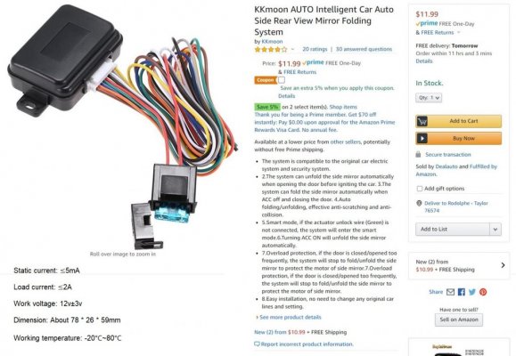
For all of you trying to achieve Mirror Autofold, I was able to add a chinese module inline with the DSM in my 2016 Limited EL and that does the trick.

Description of Operation:
- Folds the mirrors on lock (engine off)
- Unfolds the mirrors on Unlock (engine off)
- Retains Powerfold switch functionality
- Can only fold/unfold mirrors with the OEM switch when engine is running.


Amazon.JPG


I had to splice into the vehicle wiring for the following:
- 12V Constant Power
- Ground
- 12V Switched Power (Run/Start)
- Lock
- Unlock

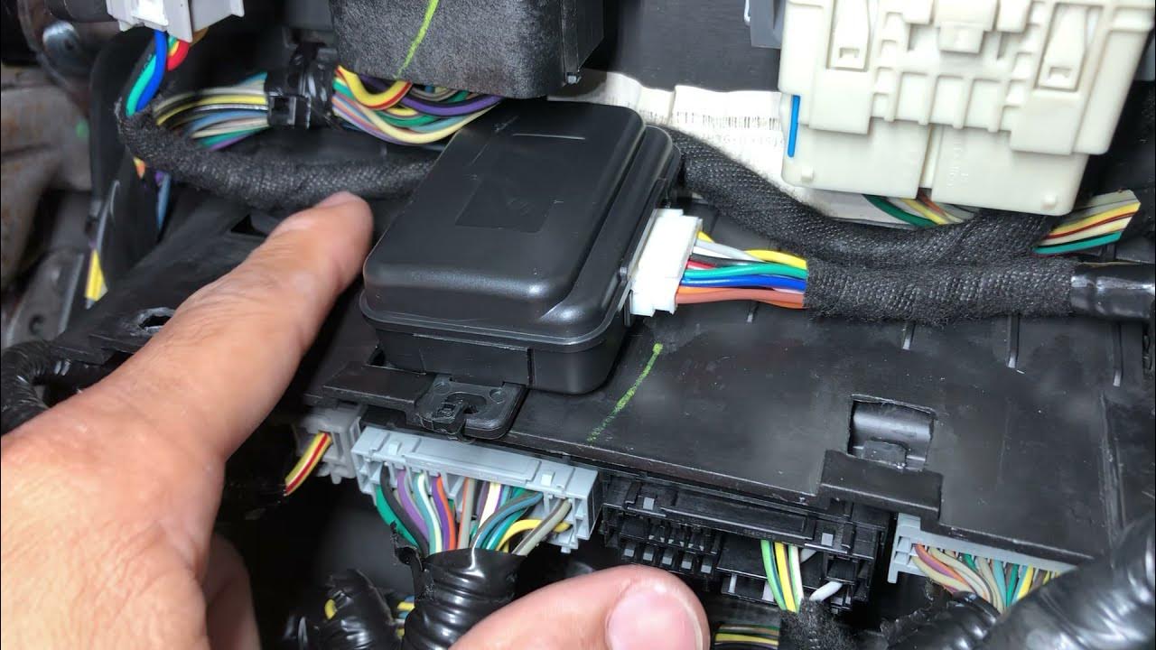
I tapped into all of these wires under the carpet under the driver seat and behind the LH kick panel.


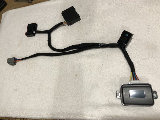
i separated the wires into a neat harness that I plugged inline with the DSM. The 2 large black connectors are a male/female set forming a T-Harness to match the DSM connector C341C, making it plug-n-play. The gray connector all the way on the left in this picture is my quick disconnect if I wanted to remove the seat from the vehicle. I ended up swapping it out with the male version of that connector. (see in next picture below this one and in the video).

IMG_6135.JPG


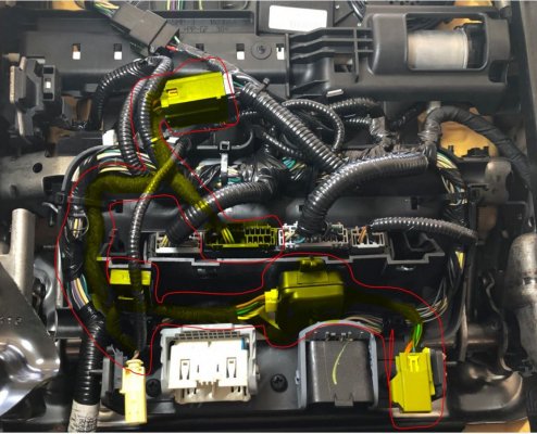
Under Driver Seat View - The Harness is everything highlighted in yellow.

Under the Seat.JPG


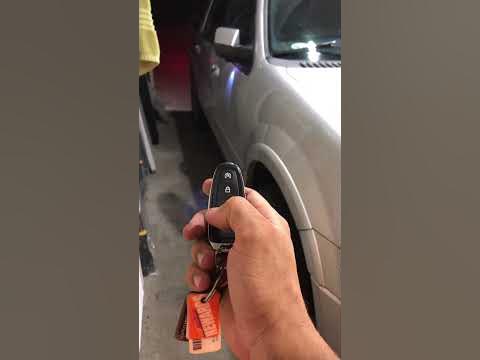
Final Result:


Hope this inspires someone to do the same.
 
Last edited:

star-art

Full Access Members
Joined
Aug 23, 2010
Posts
540
Reaction score
155
Location
Pacific Northwest
This is fantastic, thank you for sharing!! I have memory mirrors on my truck but not factory power-fold, so this could be the easiest way for me to achieve both power-fold and auto-fold in one step.

One question though: On my 2017 I checked the factory wiring diagram and could not seem to find a switched Ignition ON circuit. It seems all the various modules get the Ignition Status and Engine Running status over the network. Where did you tap a wire for your Ignition feed?

Thanks! :)
 
Top