Power windows won't work

Disclaimer: Links on this page pointing to Amazon, eBay and other sites may include affiliate code. If you click them and make a purchase, we may earn a small commission.

OP
OP
J

joeytforrest

Active Member
Joined
Jun 14, 2015
Posts
31
Reaction score
0
Location
Houston
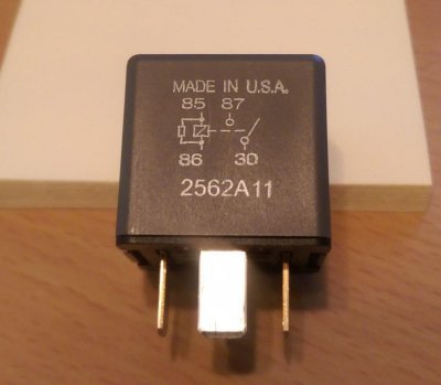
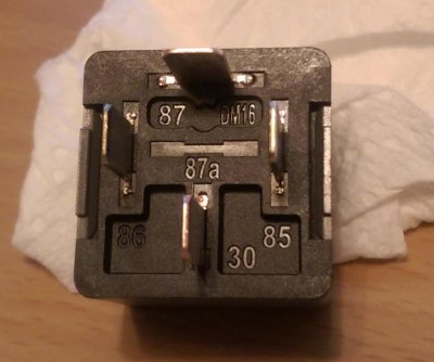
Jumped 30 to 87 and windows operated normally. Didn't mention before, but moonroof and windows above rear quarter panels were non-functional and now operate normally as well.

Is this evidence that relay is not working? I bought the relay at Ford dealership. Could I have bought a bad one? Should I just jump the relay and be done with this?

Thanks to everyone for bringing me this far and I'm glad I'm not tracing wires from the relay box under the hood.
 

Attachments

  • Relay48.jpg
    Relay48.jpg
    56.2 KB · Views: 35
Last edited:

Bedrck47

Full Access Members
Joined
Jul 4, 2014
Posts
5,641
Reaction score
652
Location
Elizebethtown, PA
You now know that the problem has to do with the relay circuit. You need to check to see if the coil is getting voltage or not

a few things you can do

Take your Volt meter and place the leads in the slots for pins 85 and 86 see if you have 12 volts at that point.

You could also make up two jumpers and connect them to pins 85 and 86 on the relay and then connect them to the 12 volt battery and then measure continuity across pins 30 and 87. When you hook up the jumper leads to the battery you should hear or feel the relay energize.

Or you can measure the resistance from pin 86 and 87
 

stamp11127

Full Access Members
Joined
Mar 10, 2012
Posts
6,218
Reaction score
1,250
Location
Temple, Georgia
Pin 86 should be hot along with pin 30. If 86 is hot you have a problem on the control side of the account delay relay. Unfortunately the diagrams show a rectangle labeled "control" and not the circuitry it contains. It's purpose is to turn the ground on and off.
Let me do some more digging on the net.
 
OP
OP
J

joeytforrest

Active Member
Joined
Jun 14, 2015
Posts
31
Reaction score
0
Location
Houston
Done:
1. Pin 86 has voltage
2. Pin 85 no voltage.
3. Connect battery directly to pins 85 and 86. I have two relays and both energized (clicking noise). 30 and 87 had continuity while relay was energized.
4. Resistance between:
*pins 85 and 87 is OL
*pins 86 and 87 is OL
*pins 85 and 86 is 65 ohms
*pin 30 and all others is OL
 
Last edited:

stamp11127

Full Access Members
Joined
Mar 10, 2012
Posts
6,218
Reaction score
1,250
Location
Temple, Georgia
Meter testing 101
Do not test any part of a circuit for ohms or continuity with an energized power supply connected, use volts or amps settings instead.

Depending on the voltage in the circuit the meter fuses may blow or the meter will explode.

For our 12v systems you will probably pop the fuse if you don't fry the meter. I show students a video of the fatal results of an electrician who bypassed safe guards and shorted an energized 2300v power supply with a Fluke meter. The man was on fire for 2 minutes before getting help and later died at the hospital.
So it is over precaution for me but anything above a "d cell" battery - pay attention to what you are doing.

Pin 85 is connected to the ground controlling portion of the circuit - which isn't working.
 
Last edited:
OP
OP
J

joeytforrest

Active Member
Joined
Jun 14, 2015
Posts
31
Reaction score
0
Location
Houston
Thank you for the tips... I don't want to fry and I understand the principle of safety first.

I'm still trying to figure out the significance of the reading so thank you for the replies...

*if 85 and 86 are the coil side of the relay, why is there no continuity (relay not charged as cautioned)

*then is it that the ground connection between slot 85 and the slot for the 30A circuit breaker broken/interrupted/bad solder?
 

Attachments

  • Relay48Circuit.jpg
    Relay48Circuit.jpg
    61.8 KB · Views: 14
Last edited:

Bedrck47

Full Access Members
Joined
Jul 4, 2014
Posts
5,641
Reaction score
652
Location
Elizebethtown, PA
If you use your ohm meter across pins 85 and 86 of the coil you should get a reading of 65 to 70 ohme see attached
I have a relay on my desk and the 65-70 reading is what I got on that relay

The print is from a 03 expedition but the relays are the same for the 08
 

Attachments

  • 149-41.pdf
    19.4 KB · Views: 33
Last edited:
OP
OP
J

joeytforrest

Active Member
Joined
Jun 14, 2015
Posts
31
Reaction score
0
Location
Houston
Yep, I have two relays and one is 65 ohms between pins 85 and 86, while the other is 68 ohms. Just curious why I have ohms but no continuity. I'm a novice so I'm learning about circuitry as I go.
 
Last edited:
Top