Added USB-C Charger

Disclaimer: Links on this page pointing to Amazon, eBay and other sites may include affiliate code. If you click them and make a purchase, we may earn a small commission.

STINNETT

Well-Known Member
Joined
Jan 27, 2021
Posts
77
Reaction score
64
Location
Memphis, TN
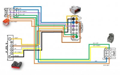
The 3 black dots represent the splices you'll have to make into the existing Expedition inverter harness. (If you have one from factory)

Pin 4 of C2293 is the additional Terminal needed for the Dash AC/DC outlet LED indicator.

THIS IS A MODIFIED WIRING DIAGRAM TO ILLUSTRATE THIS PROJECT
View attachment 41740


Thank you!

I've started collecting the parts to do this. I just got my F150 Dash AC/DC Outlet Combo FL3Z-19A487-B in the mail yesterday and shopping for the other pieces.
 

STINNETT

Well-Known Member
Joined
Jan 27, 2021
Posts
77
Reaction score
64
Location
Memphis, TN
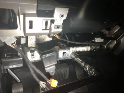
I think I may be confused. Are you replacing the existing 150w inverter with the 400w inverter and adding the dash port? OR are you adding 400w inverter just for the dash? Sorry brain on meltdown today. Where is the stock inverter on the Expy located?
 
OP
OP
T

TXFRDOwner

Full Access Members
Joined
Jan 21, 2010
Posts
411
Reaction score
208
Location
Texas
I think I may be confused. Are you replacing the existing 150w inverter with the 400w inverter and adding the dash port? OR are you adding 400w inverter just for the dash? Sorry brain on meltdown today. Where is the stock inverter on the Expy located?

Exactly, I replaced my Expy’s 150W with the F150’s 400w inverter.

Replace my 150W Expedition Inverter with the F150's (400W) dual AC Outlet. The Inverter I bought on ebay came with pigtails. I made my own Harness adapter so I wouldn't have to cut into the existing Expedition harness.

IMG_6024.JPG

MOD - Inverter Plug Harness Adapter.jpg


The Inverter mounts behind the Dash on the driver side. Full Disclosure, this is an awkward spot to mount anything in but it can be done with some conviction. I used short self tapping screws.


03BE2763-5E9A-48A1-A9CF-CC2798D323CC.jpeg


The opening for the AC outlet required some sanding to enlarge it so the F150 Outlet would fit. Made an extremely big rookie mistake ... I forgot to use masking tape around the edges, now i'm left with some scuff marks. Learn from my mistakes :)

I used a flat wooden stick (paint stirrer) with 180 & 320-grit sand paper. The areas I focused my attention on were the top, bottom and right sides of the opening. More so the top. I ended up having to sand the bottom left corner of the AC Outlet also to make it fit.

Could've done without the scuff marks but I'm happy with the results.


AE84BFBC-F1CE-44C5-A8E6-FBB53E18ABDC.jpeg


684E0D9E-0737-4987-9EE5-EA2F8088DFE4.jpeg


Hope I didnt scare y'all off .. :signs8:


Go here to see a few more pics. Happy to answer any questions you may have.

https://drive.google.com/drive/folders/12ohi_h-V0SjTN1P1YL9ZIsde8ZpOhlNp?usp=sharing
 
Last edited:

STINNETT

Well-Known Member
Joined
Jan 27, 2021
Posts
77
Reaction score
64
Location
Memphis, TN
Great! Thanks!

#1 where is the inverter located in expedition?

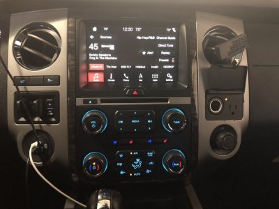
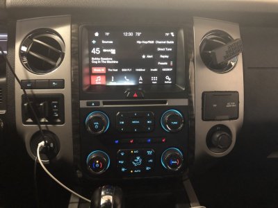
#2 how'd you get black interface on Sync? Is that 3.4?

Sent from my SM-N986U1 using Tapatalk
 
OP
OP
T

TXFRDOwner

Full Access Members
Joined
Jan 21, 2010
Posts
411
Reaction score
208
Location
Texas

Langer

Full Access Members
Joined
Mar 27, 2019
Posts
459
Reaction score
197
Location
Chicago
Exactly, I replaced my Expy’s 150W with the F150’s 400w inverter.

Replace my 150W Expedition Inverter with the F150's (400W) dual AC Outlet. The Inverter I bought on ebay came with pigtails. I made my own Harness adapter so I wouldn't have to cut into the existing Expedition harness.

View attachment 41928

View attachment 41929


The Inverter mounts behind the Dash on the driver side. Full Disclosure, this is an awkward spot to mount anything in but it can be done with some conviction. I used short self tapping screws.


View attachment 41925


The opening for the AC outlet required some sanding to enlarge it so the F150 Outlet would fit. Made an extremely big rookie mistake ... I forgot to use masking tape around the edges, now i'm left with some scuff marks. Learn from my mistakes :)

I used a flat wooden stick (paint stirrer) with 180 & 320-grit sand paper. The areas I focused my attention on were the top, bottom and right sides of the opening. More so the top. I ended up having to sand the bottom left corner of the AC Outlet also to make it fit.

Could've done without the scuff marks but I'm happy with the results.


View attachment 41924


View attachment 41923


Hope I didnt scare y'all off .. :signs8:


Go here to see a few more pics. Happy to answer any questions you may have.

https://drive.google.com/drive/folders/12ohi_h-V0SjTN1P1YL9ZIsde8ZpOhlNp?usp=sharing


Can you elaborate on the adaptor you made so you didn’t have to splice? I just ordered the parts you’ve listed and would love to follow what you did to the letter (dash scuff free, hopefully )
 
OP
OP
T

TXFRDOwner

Full Access Members
Joined
Jan 21, 2010
Posts
411
Reaction score
208
Location
Texas
@TXFRDOwner
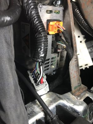
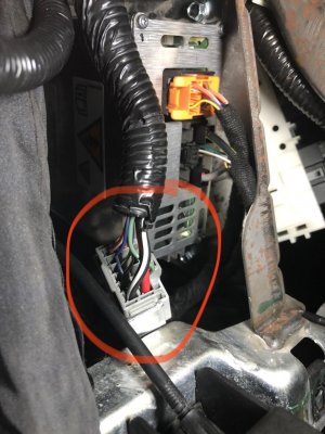
It looks like I have this big connector, mine is green rather than gray, but is that what the inverter is getting power from?
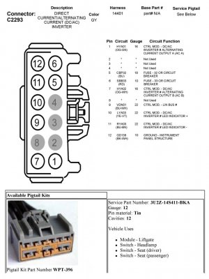
yes, the gray one is the Expedition's original inverter connector ... I made the pug-n-play harness to piggyback off of it.


C2293 - Pwr Inverter Connector.jpg
 

Langer

Full Access Members
Joined
Mar 27, 2019
Posts
459
Reaction score
197
Location
Chicago
yes, the gray one is the Expedition's original inverter connector ... I made the pug-n-play harness to piggyback off of it.


View attachment 41938


Dang, maybe my truck doesn’t have that. I only pulled off the black panel (the one the OBD2 port touches), not the side panel, but when I looked under there on the inverter side of the inverter mount point I didn’t see a big plug. The one I thought was that plugs into a green port behind the side kick panel.
 

Langer

Full Access Members
Joined
Mar 27, 2019
Posts
459
Reaction score
197
Location
Chicago
@TXFRDOwner where are you getting all these awesome wiring diagrams? I may be in for a bigger chore than I had hoped if it ends up I don’t have that inverter pigtail. I’m going to tear into it this week more thoroughly to check for sure.
 
OP
OP
T

TXFRDOwner

Full Access Members
Joined
Jan 21, 2010
Posts
411
Reaction score
208
Location
Texas
@TXFRDOwner where are you getting all these awesome wiring diagrams? I may be in for a bigger chore than I had hoped if it ends up I don’t have that inverter pigtail. I’m going to tear into it this week more thoroughly to check for sure.

I purchased a 5-Year subscription at Alldatadiy.com for the 2015 Expedition Workshop Service Manual.

I’m not gonna lie, this mod is not for the novice or for the faint of heart. [emoji41]


Sent from my iPhone using Tapatalk
 
Last edited:

Langer

Full Access Members
Joined
Mar 27, 2019
Posts
459
Reaction score
197
Location
Chicago
I purchased a 5-Year subscription at Alldatadiy.com for the 2015 Expedition Workshop Service Manual.

I’m not gonna lie, this mod is not for the novice or for the faint of heart. [emoji41]


Sent from my iPhone using Tapatalk

even if I don’t have the pigtail I think I’m arrogant enough to try. I bought the allsatadiy subscription, figure I’ll use it for other stuff, too. My biggest question is, does the splice for the inverter coming off the main harness have the same colored wires as the main harness? I’m having trouble finding that info based on what I’ve seen thus far on the website. I’m having some difficulty navigating it, and, more often than not, stumble upon what I’m looking for rather than where I would logically think I would find it.
 
OP
OP
T

TXFRDOwner

Full Access Members
Joined
Jan 21, 2010
Posts
411
Reaction score
208
Location
Texas
even if I don’t have the pigtail I think I’m arrogant enough to try. I bought the allsatadiy subscription, figure I’ll use it for other stuff, too. My biggest question is, does the splice for the inverter coming off the main harness have the same colored wires as the main harness? I’m having trouble finding that info based on what I’ve seen thus far on the website. I’m having some difficulty navigating it, and, more often than not, stumble upon what I’m looking for rather than where I would logically think I would find it.

To find the power inverter diagram, Look under diagrams-> electrical diagrams -> horn & cigar lighters


Sent from my iPhone using Tapatalk
 
Top